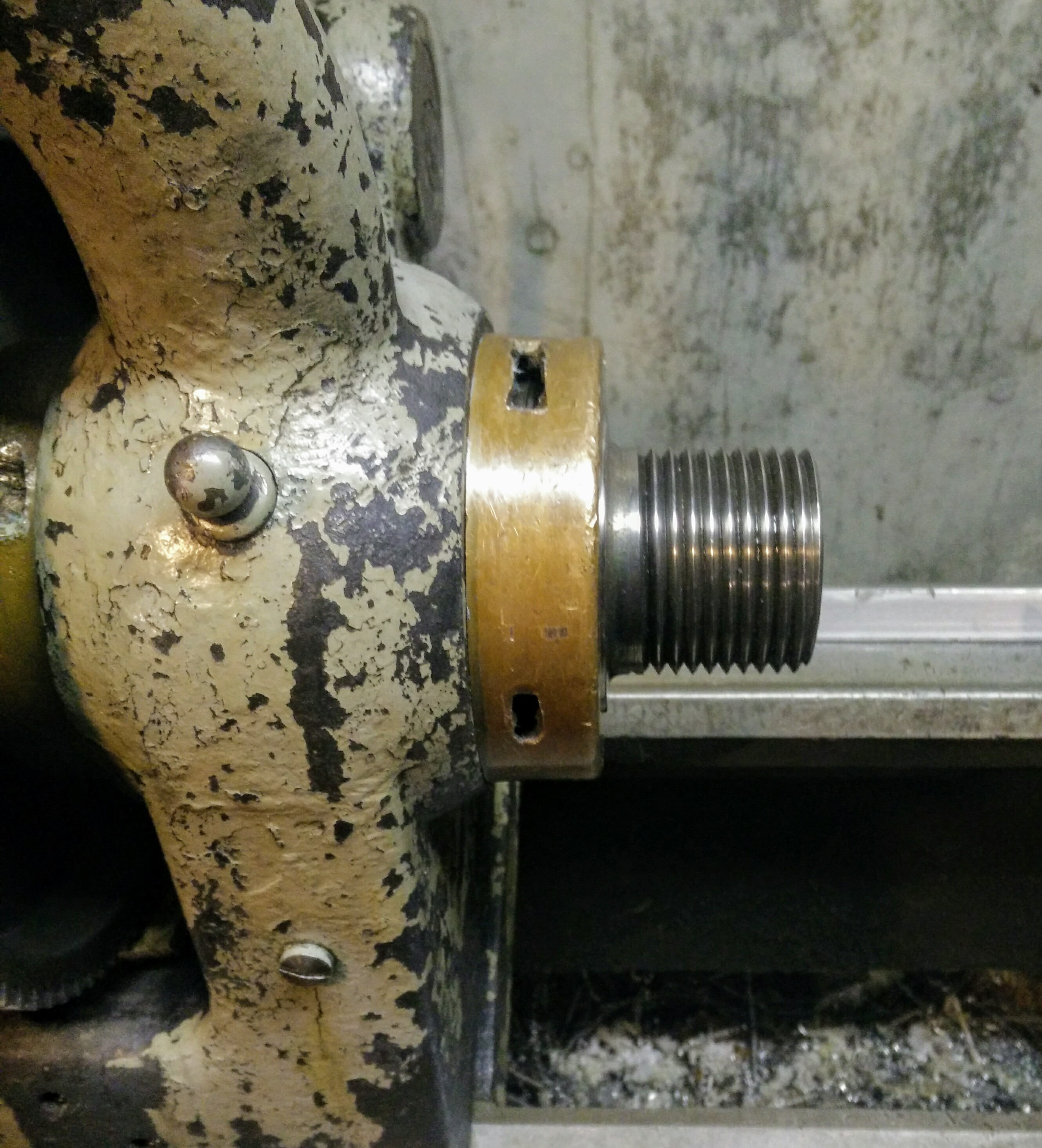
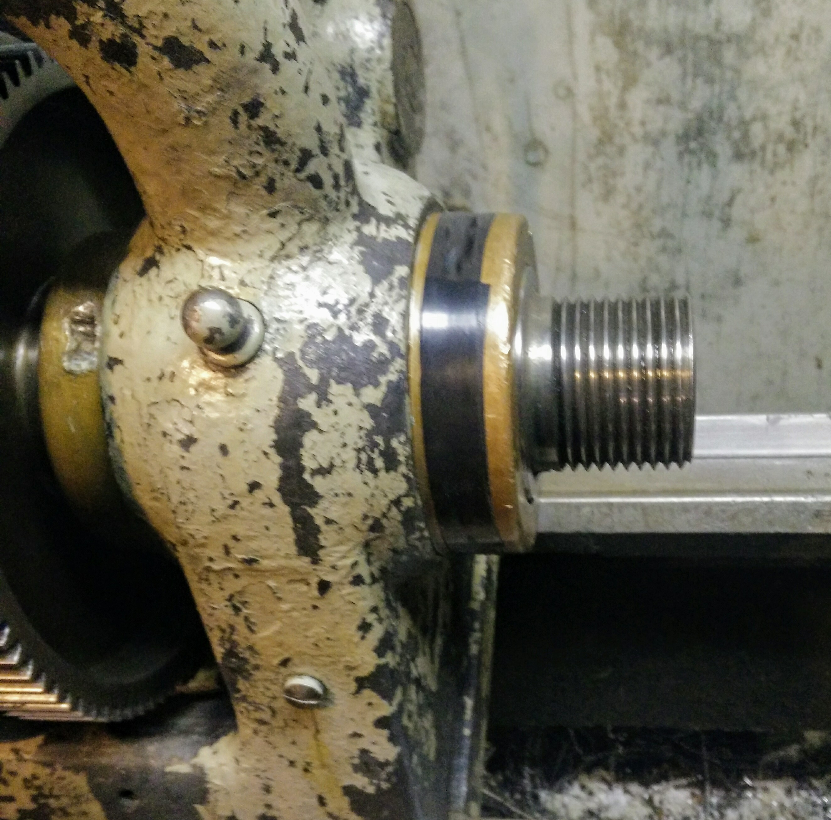
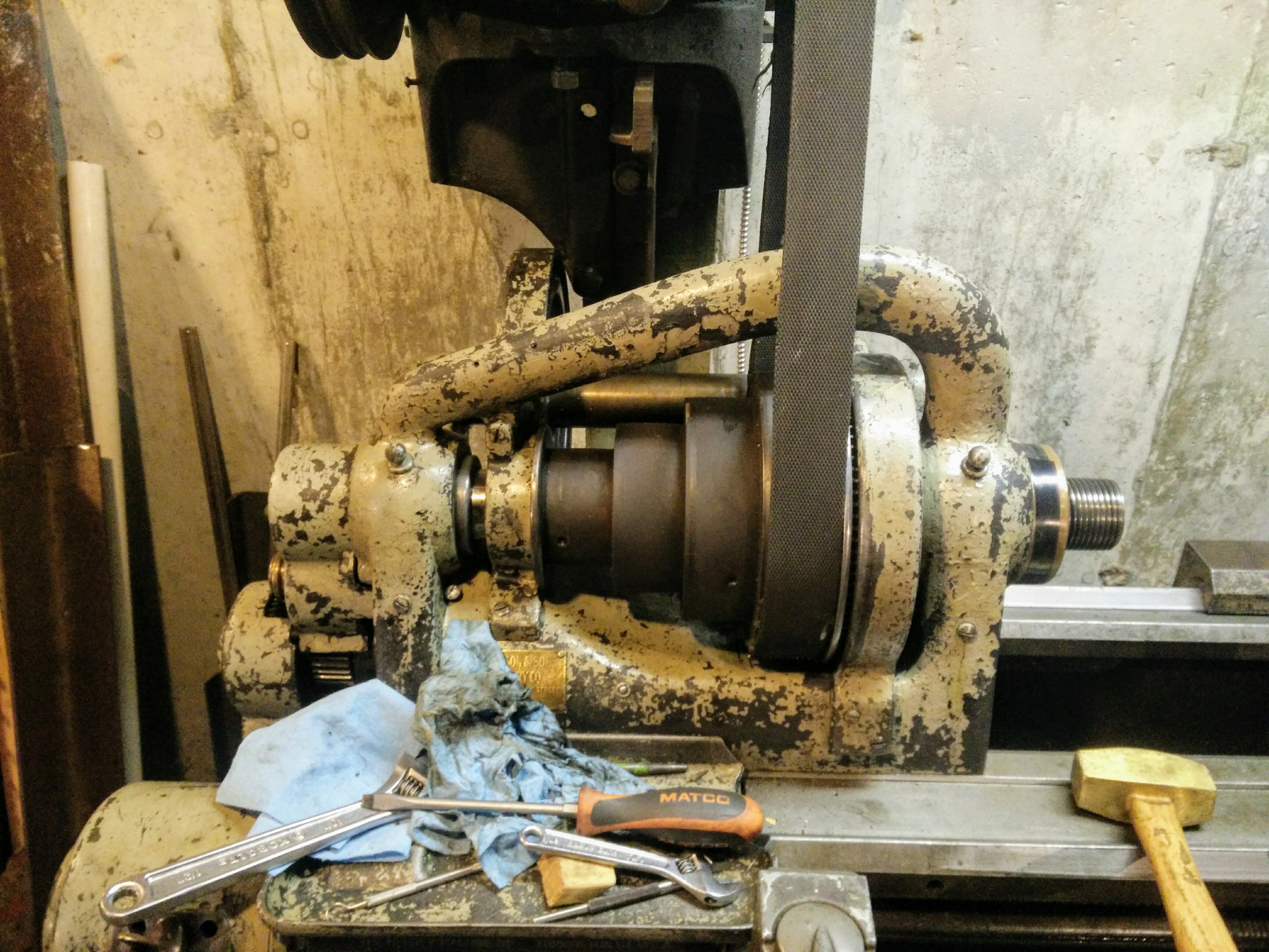
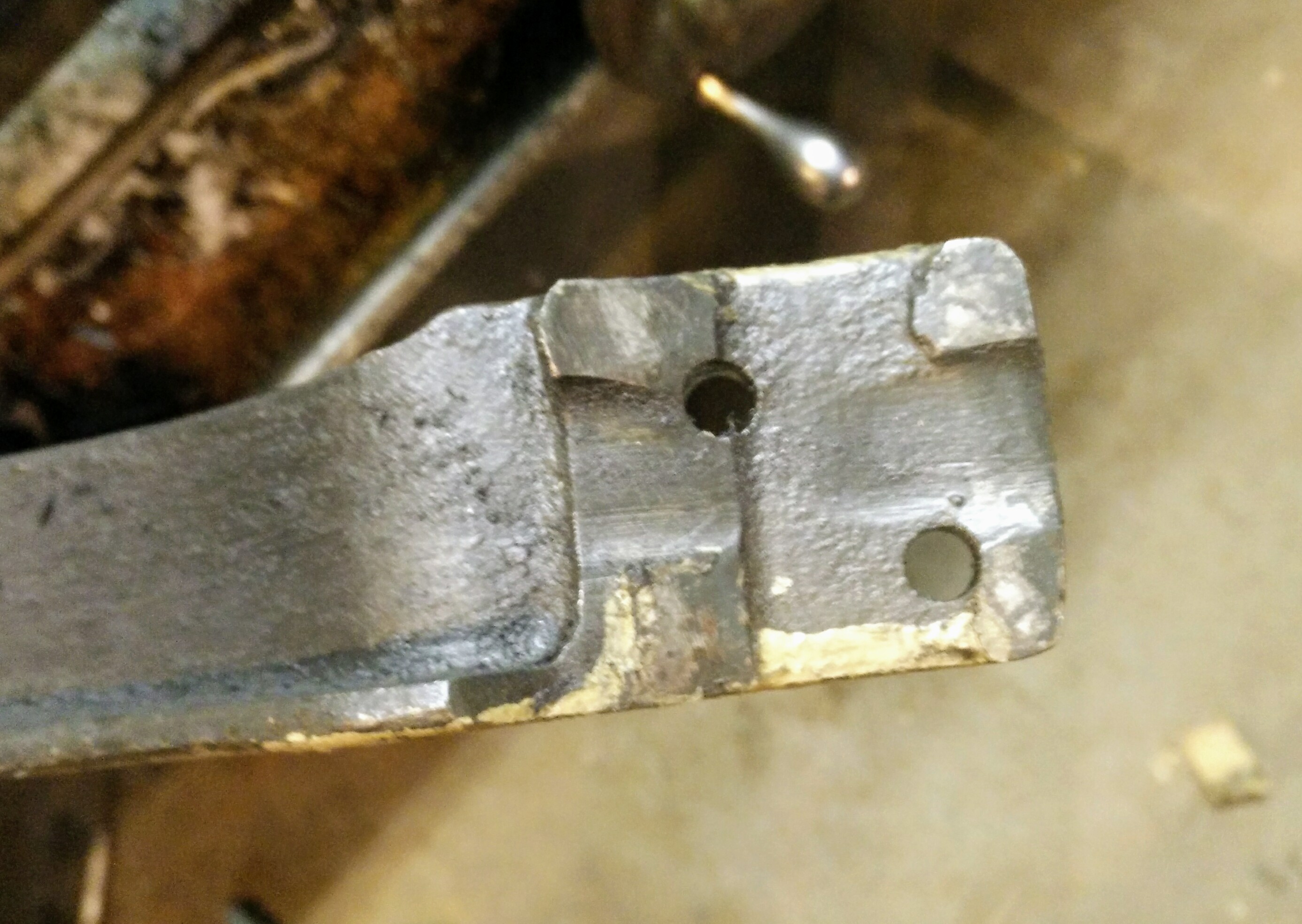
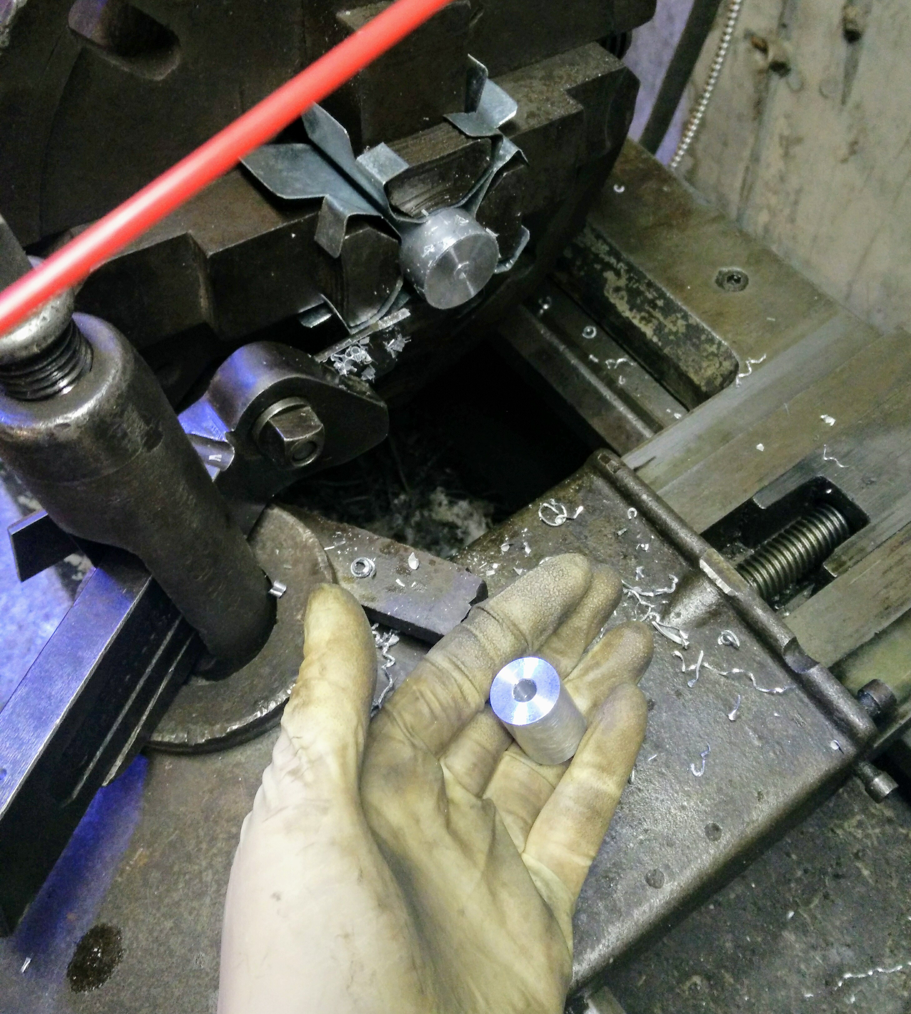
The spindle is a key component of the lathe. At one end, workpieces are held via a chuck attached to the spindle. At the other, a gear attaches to a gear train which drives the automatic feed and screw-cutting features of the lathe.
Ideally, spindle bearings have no play either radially or axially and are able to withstand any amount of force in either direction without locking up or destroying themselves. Practically, spindle bearings must make some concessions here, but the fewer the better as their performance determines the ability of the machine to take deep cuts, produce beautiful finishes, and turn parts precisely.
My lathe's spindle bearings would heat up the bearing housings until the spindle stopped turning in about half an hour of work at low speeds. Fortunately, the bearings on this lathe are adjustable, allowing them to continue being useful even after years of wear. So, I took my lathe's headstock apart to repair them!
Cleanup
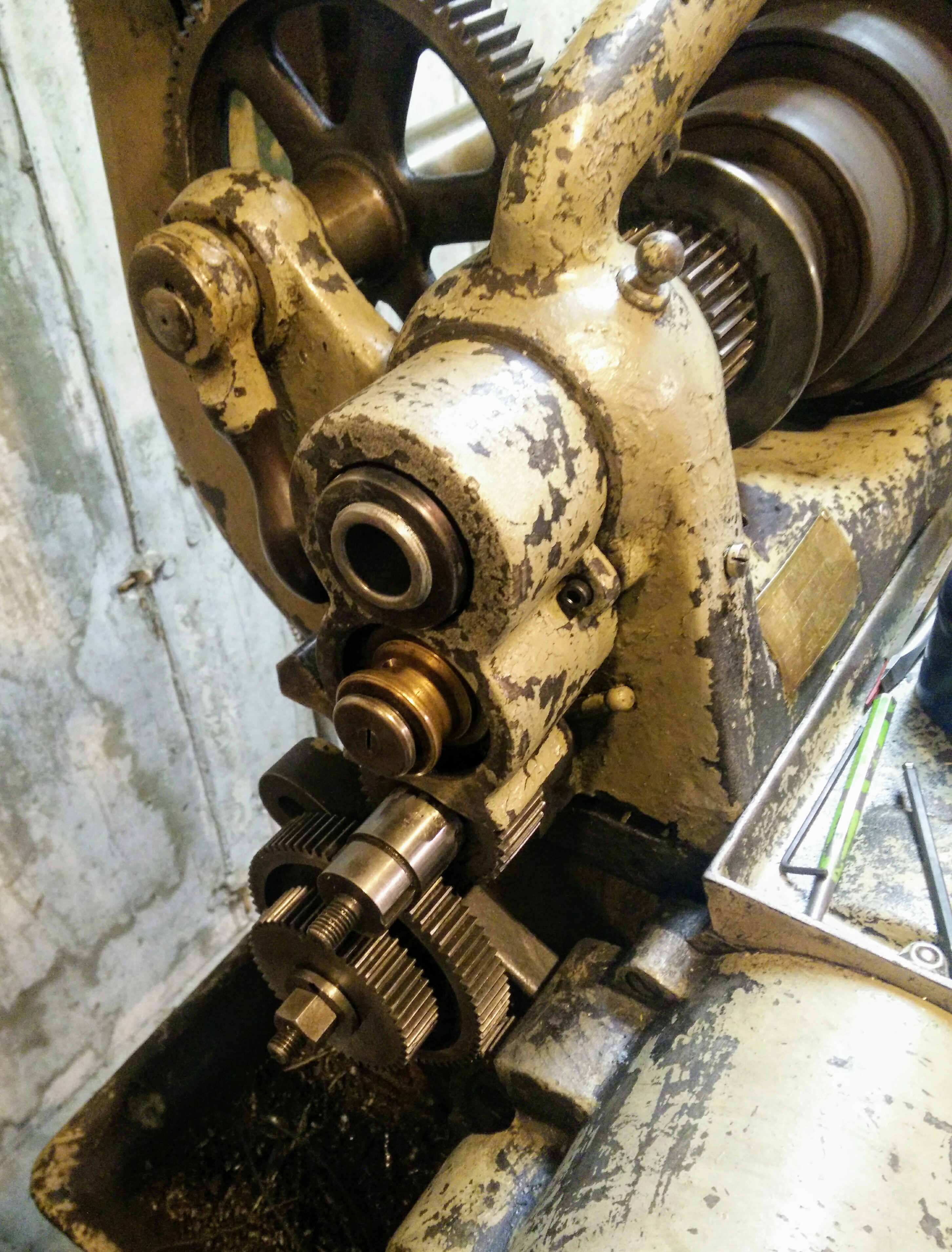
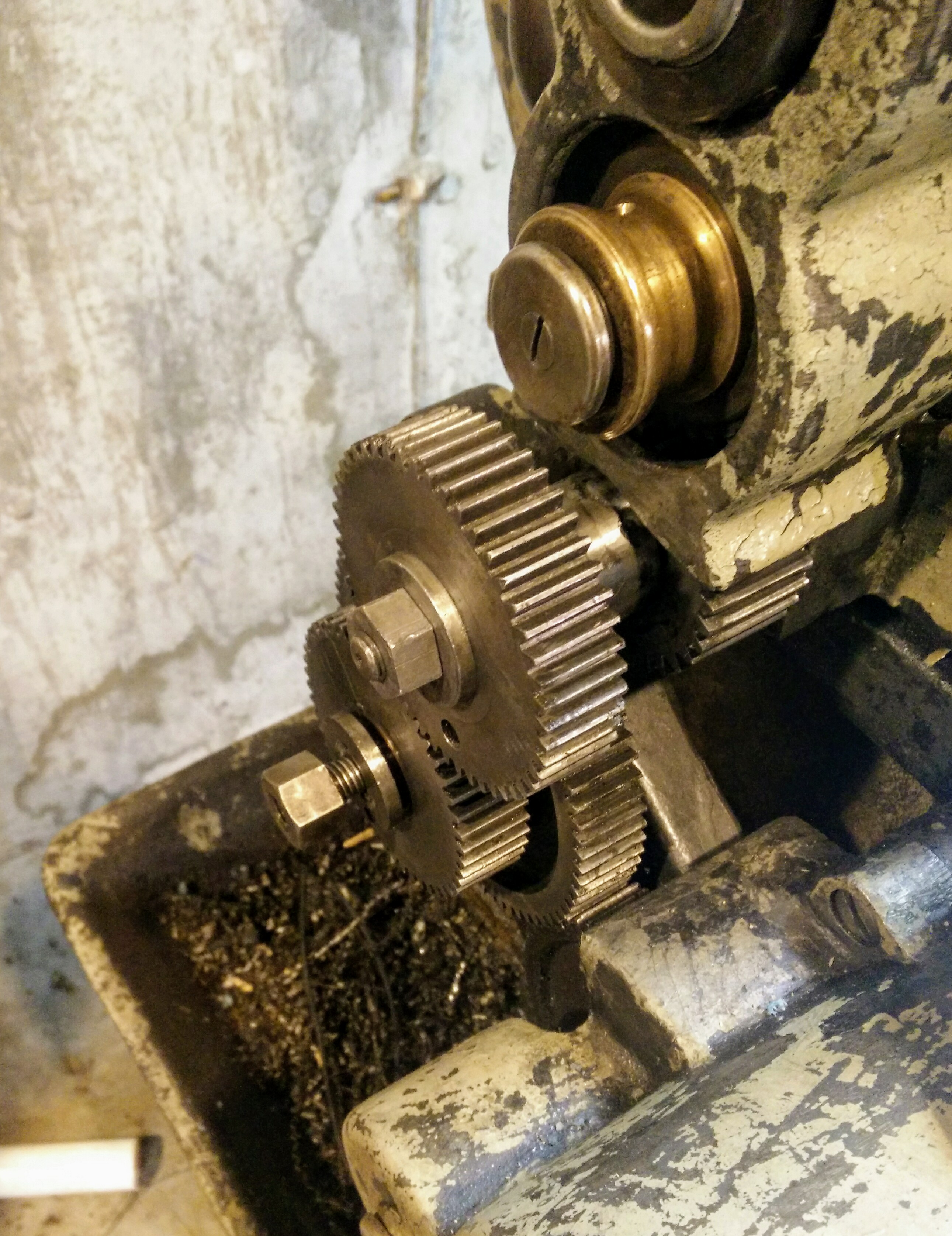
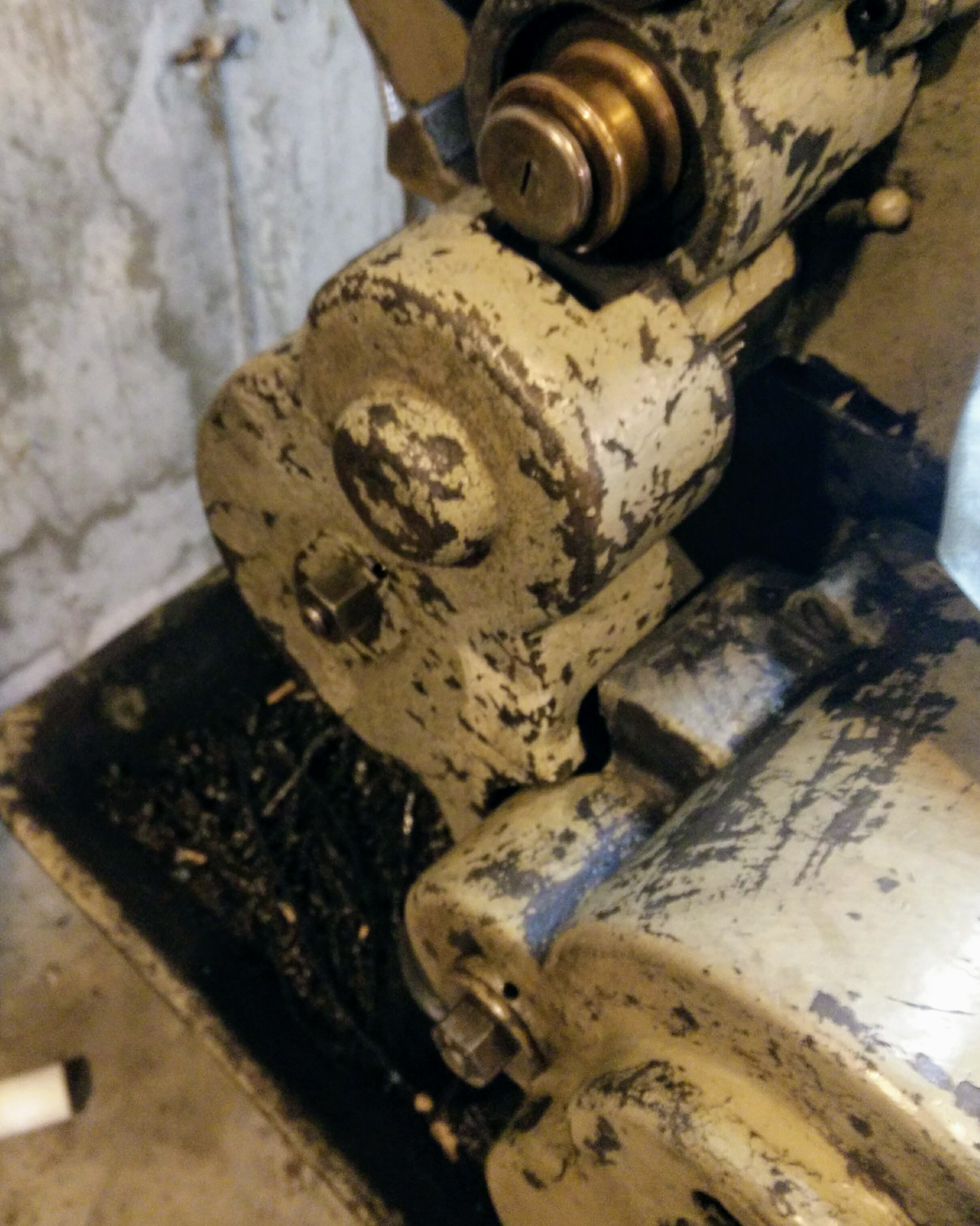
This lathe is absolutely disgusting; I don't think it's been cleaned in decades, and at some point someone slathered a bunch of grease all over it which really just makes everything worse. Taking the spindle apart gave me access to a lot of otherwise inaccessible bits, and since I don't intend on taking this apart more than is necessary, I got to scrubbing. I ended up cleaning a fair bit of the headstock, including everything that gets touched regularly.
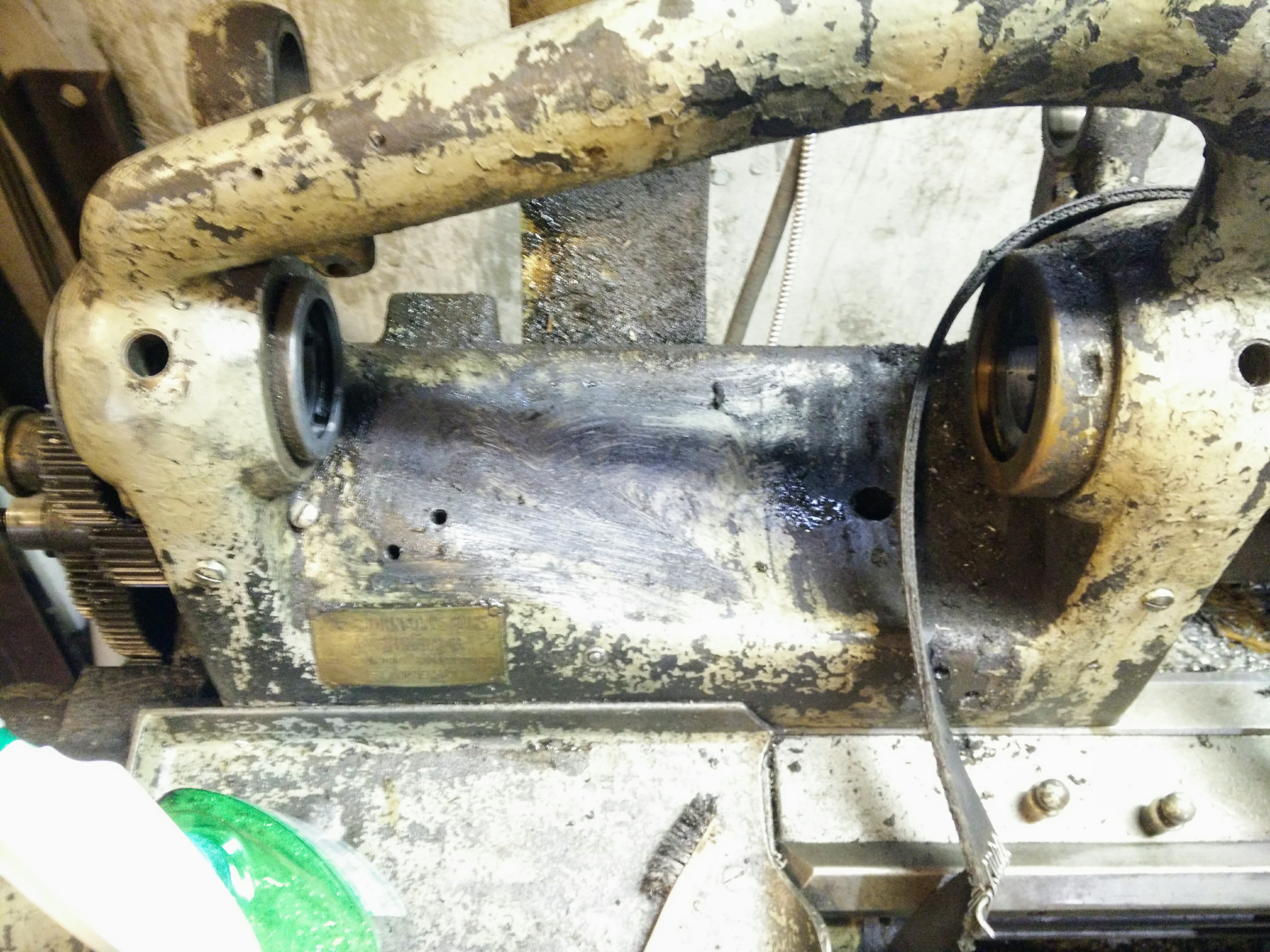
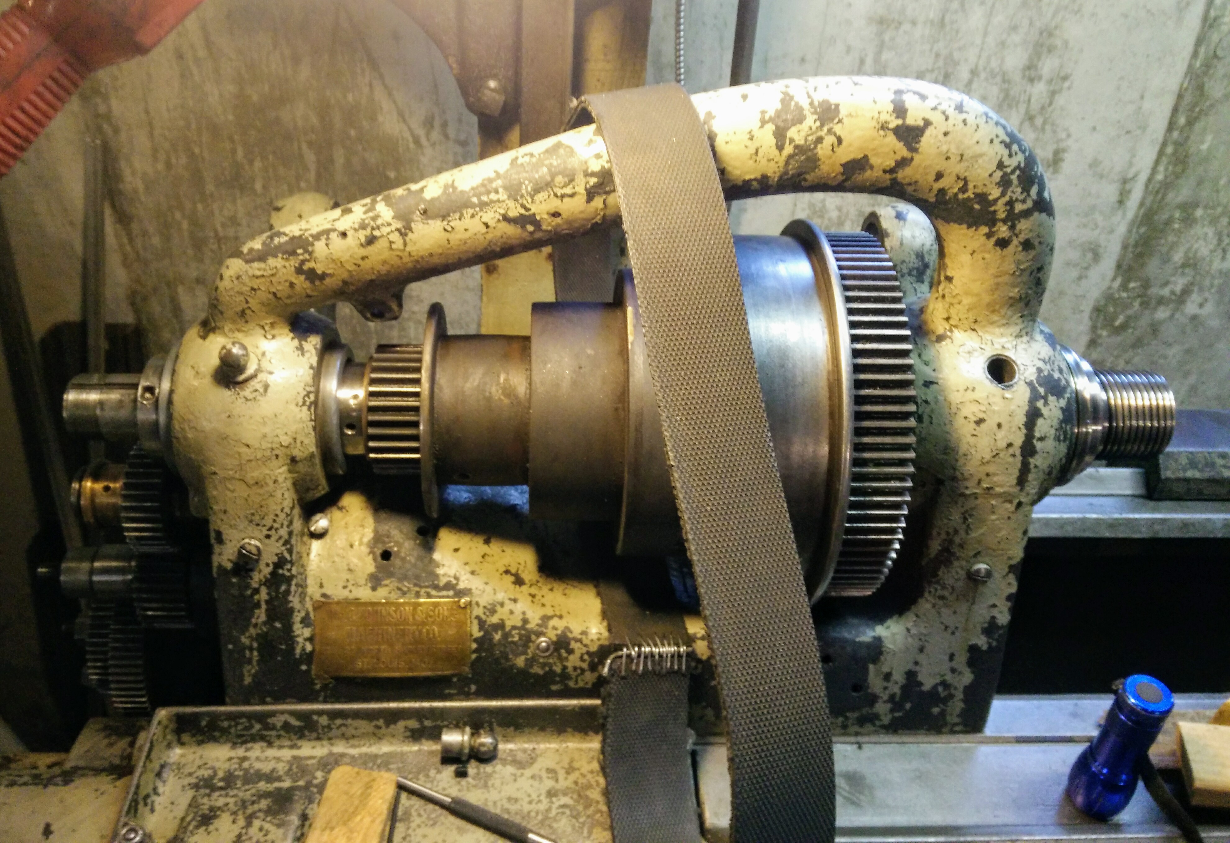
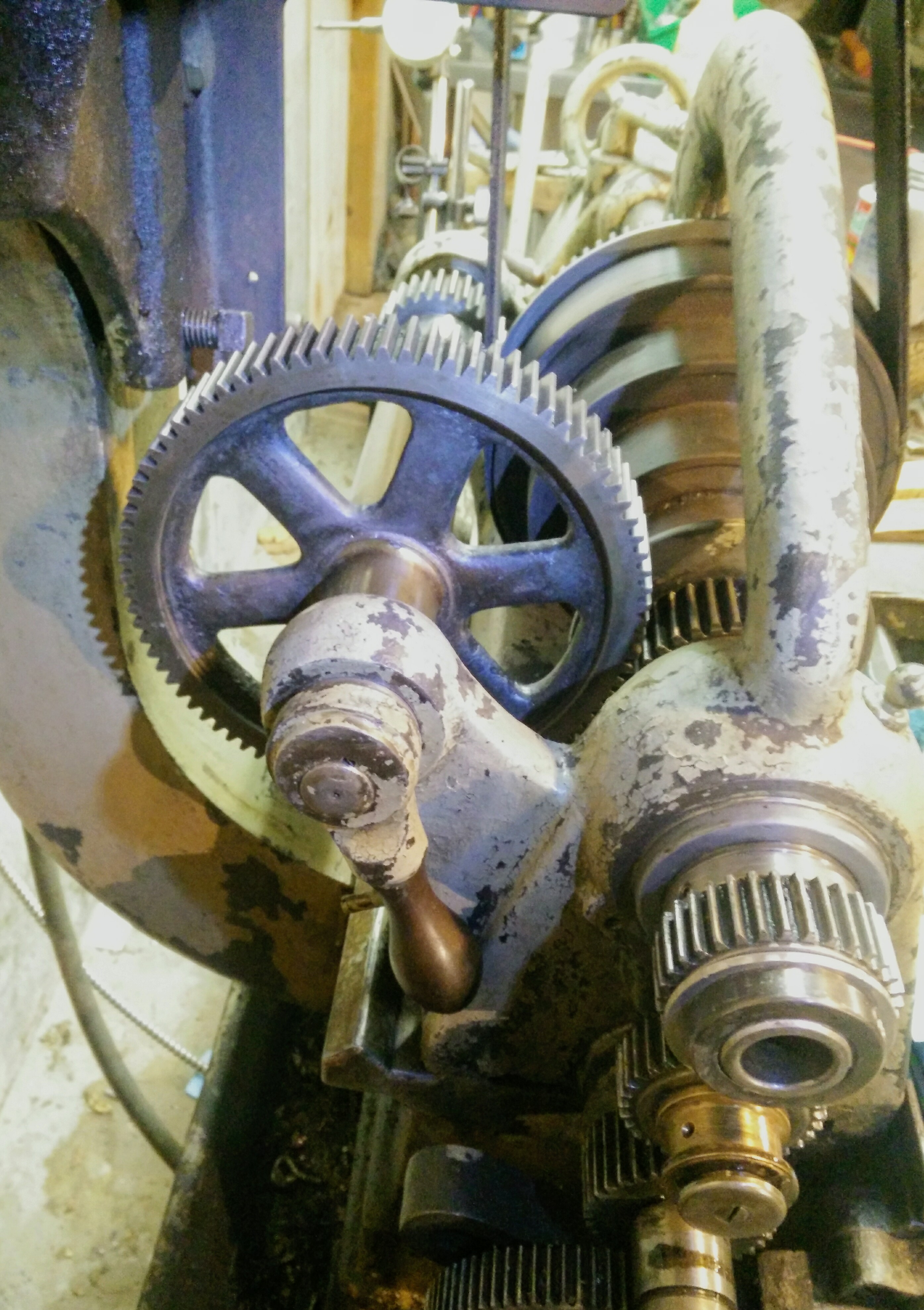
Front of the headstock with the spindle out:
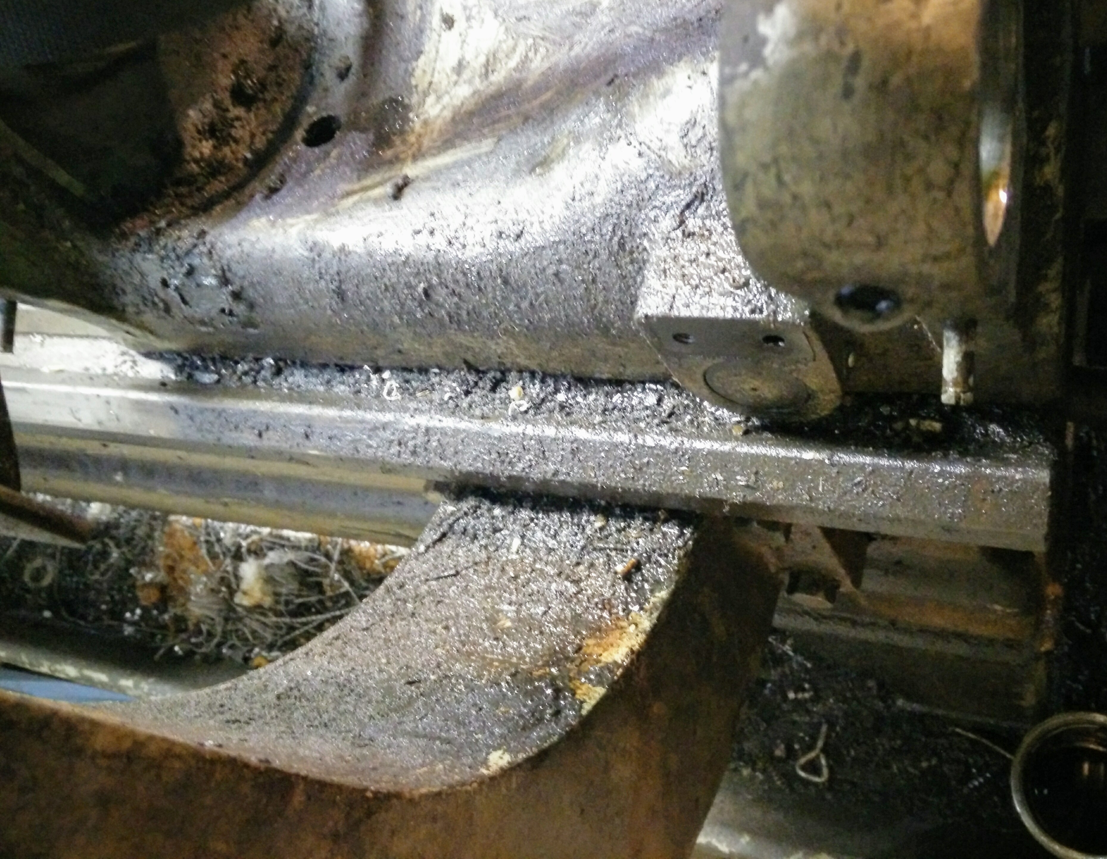
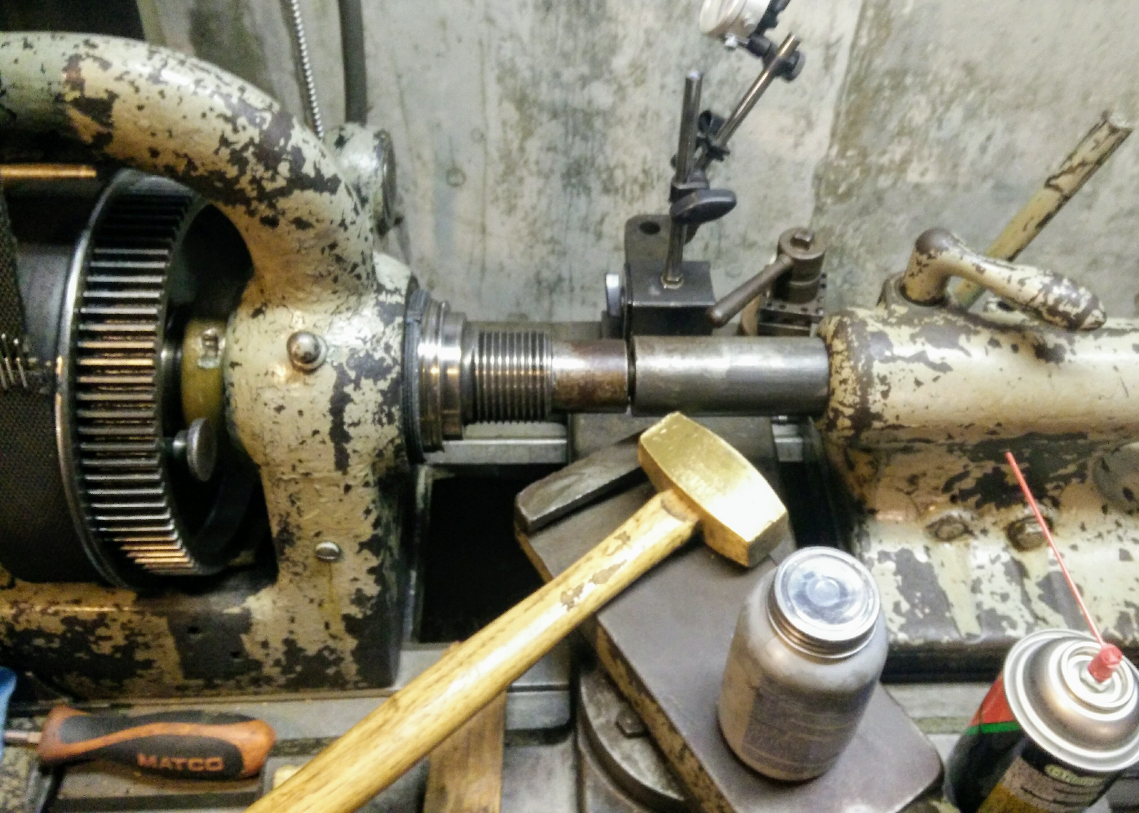
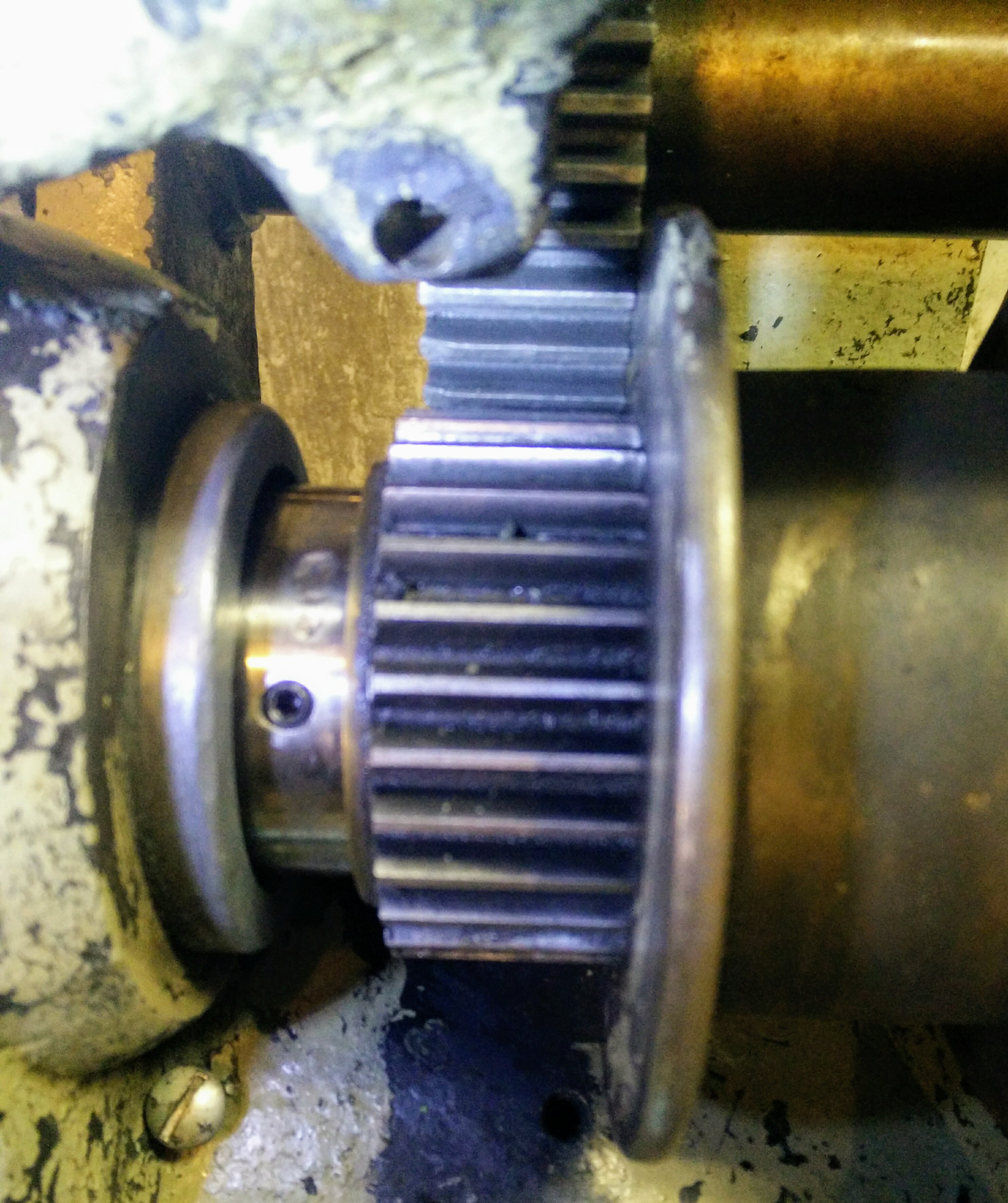
Rear:
I used up a roll and a half of those blue shop towels and a whole can of carb cleaner degreasing it. The best tool for cleaning, though, is a scraper paired with a vacuum. I also got quite some use out of a dental pick for cleaning out screw heads and holes and odd corners.
A diversion into gear shaft oiling
This lathe was made in 1918 following designs that date from the 1890s. Back in those days, "machine oiling system" and "apprentice" were synonyms. The spindle bearings have an automatic oiling system; all the other rotating parts of the lathe are lubricated by someone with patience and an oil can. There are a couple dozen oiling points hidden all over the lathe that deliver oil places one way or another.
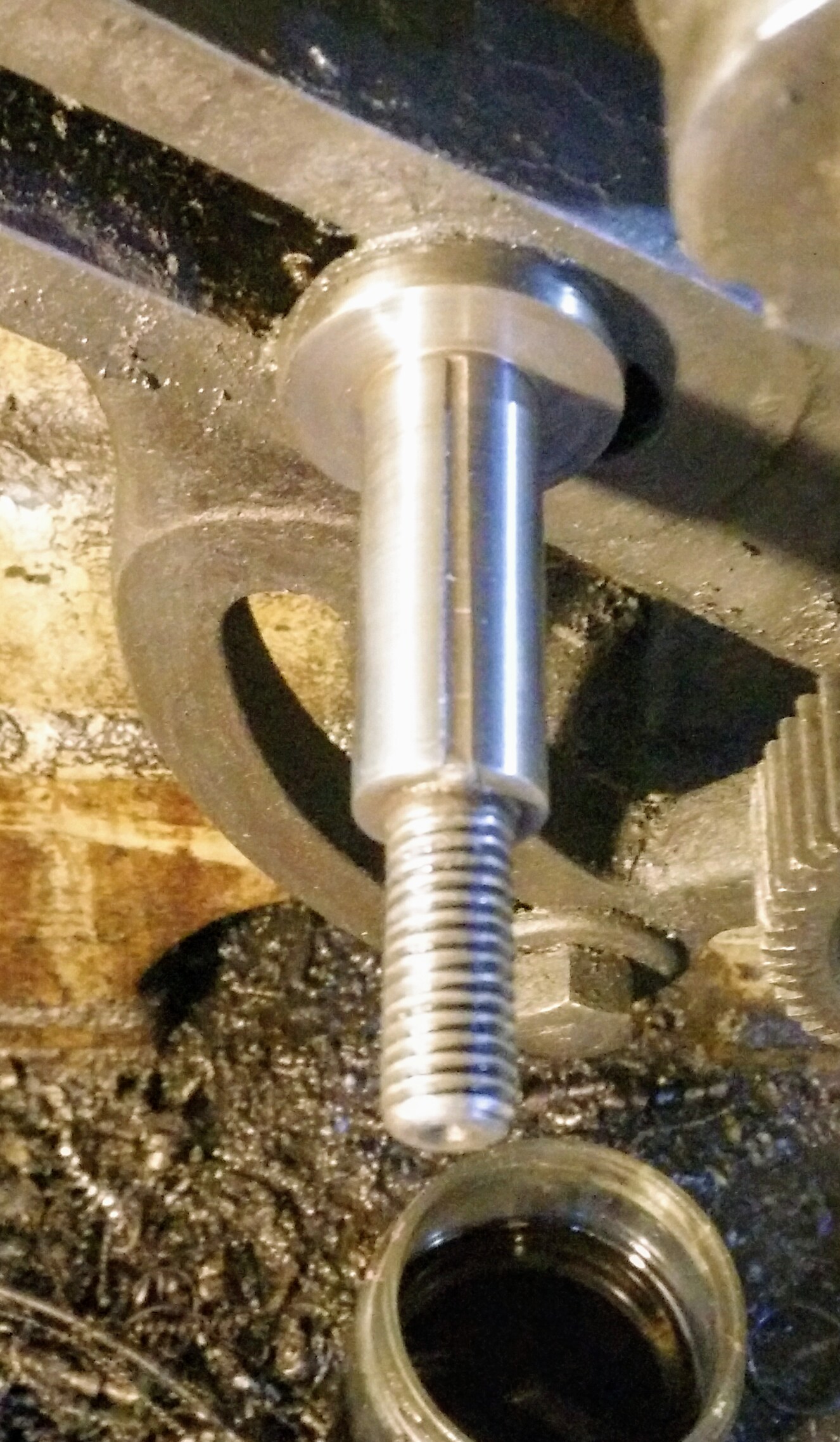
For a couple of the shafts in the gear train, the oil 'reservoir' is a groove milled into the top of the shaft:
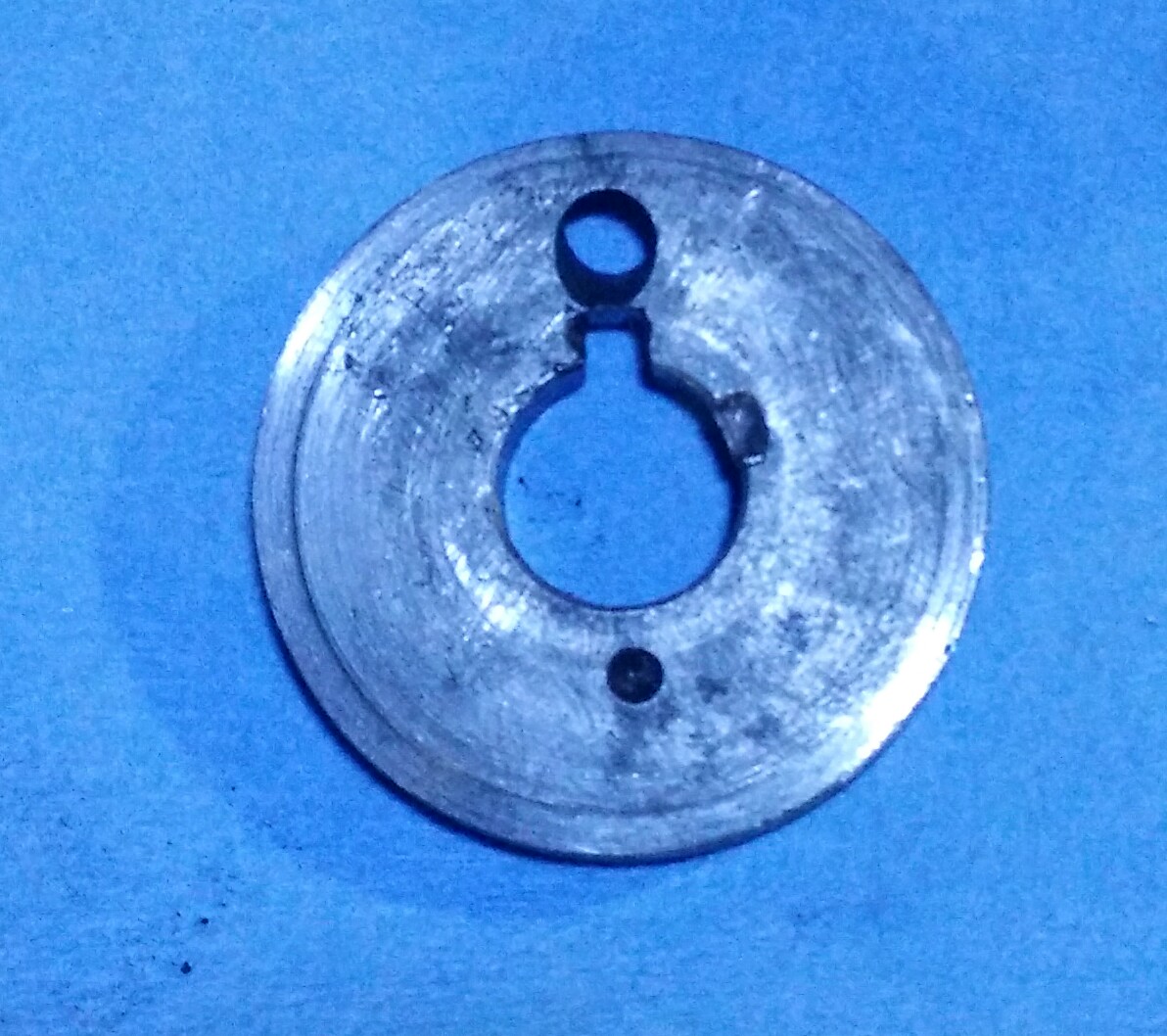
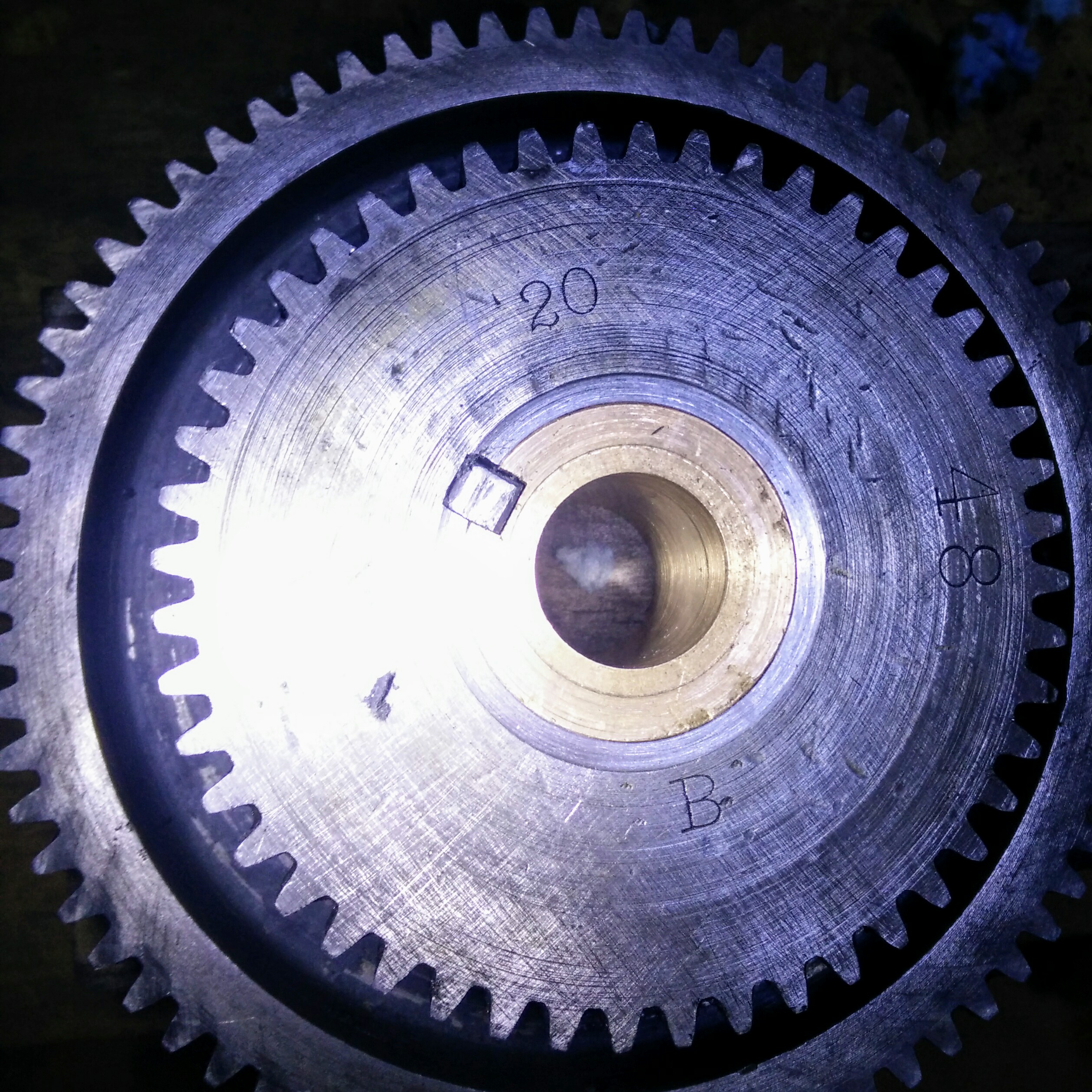
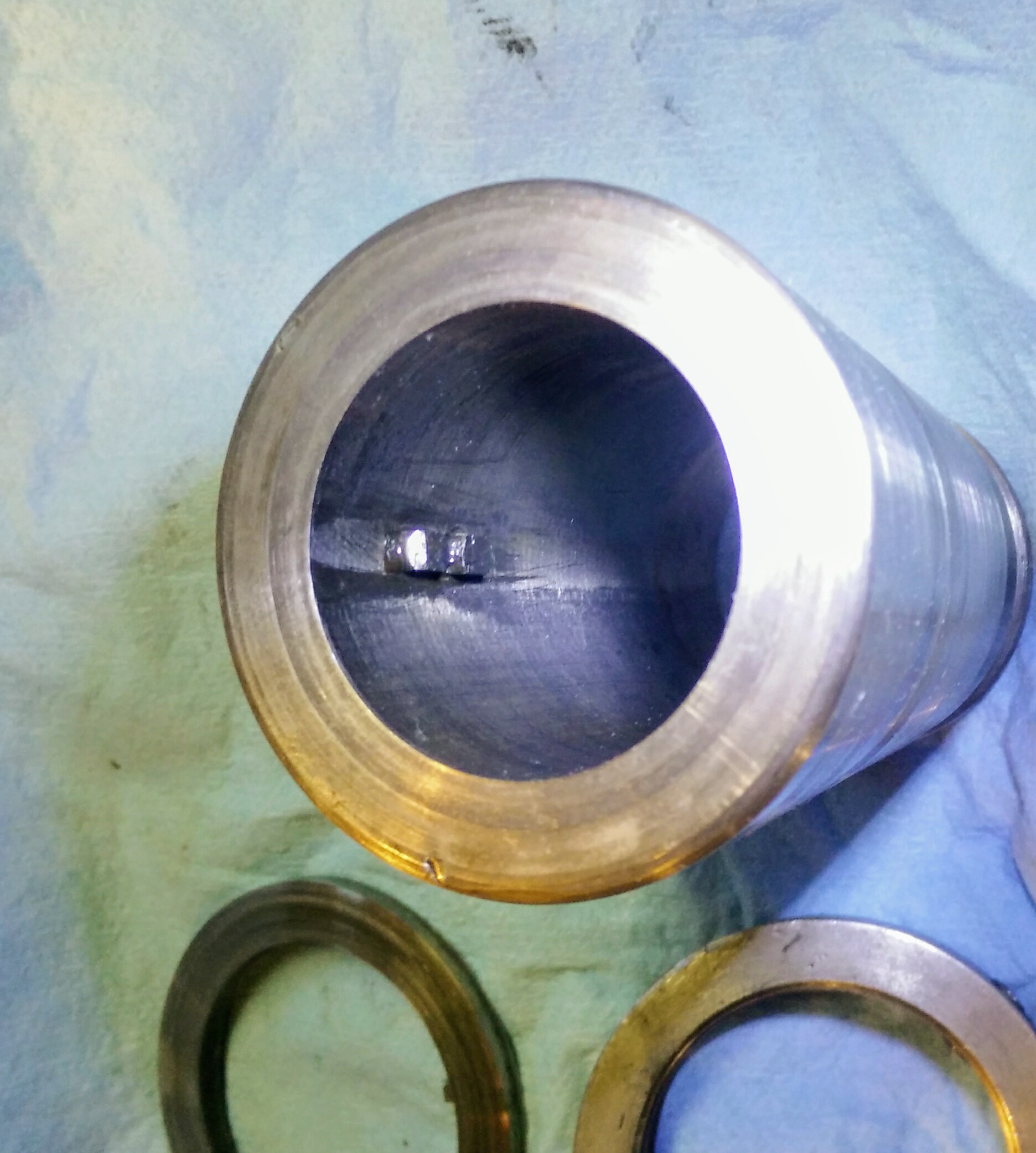
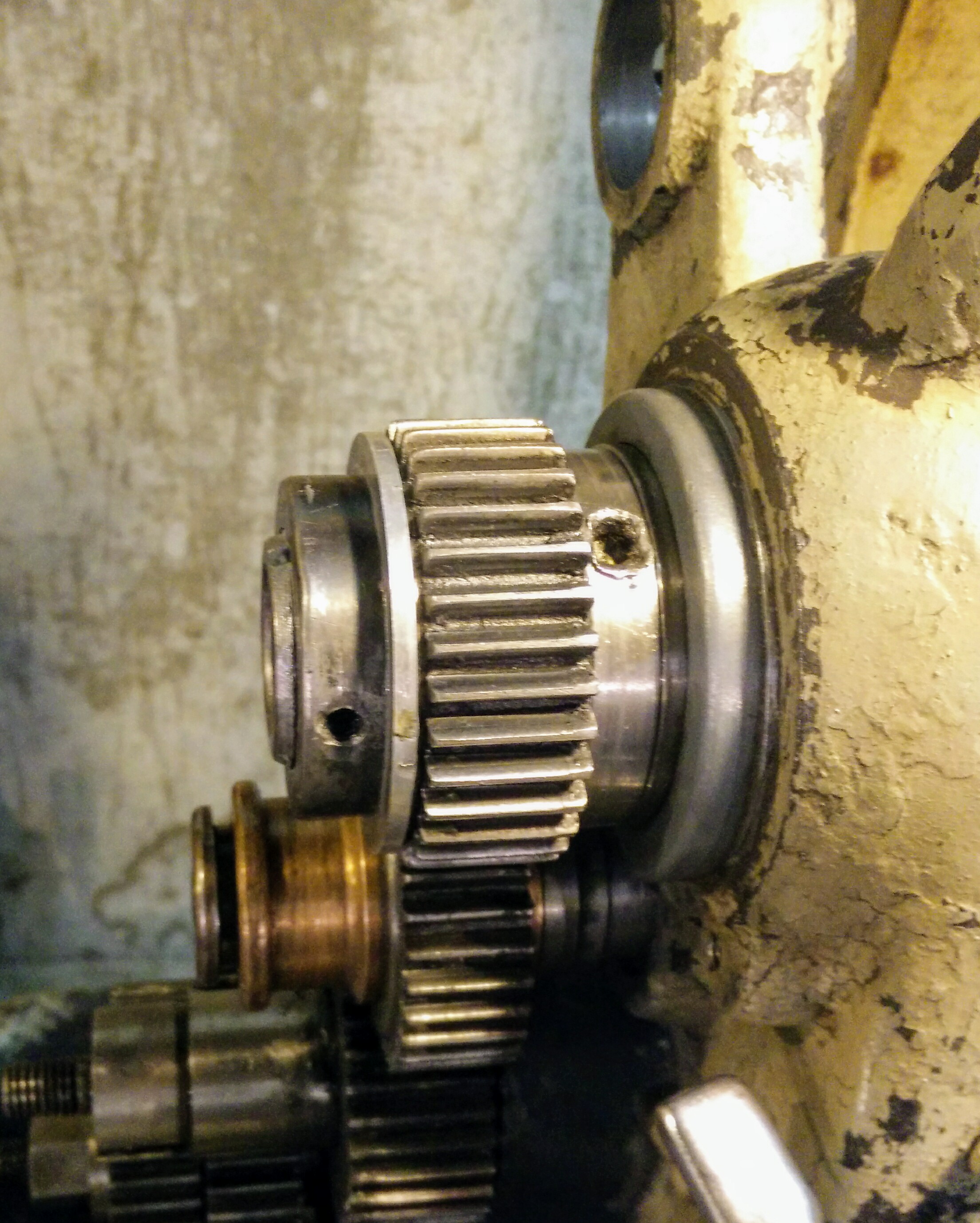
A gear slides over the shaft and is held in place via a thrust washer and a nut. The thrust washer, in turn, has a little hole in it and a slot that sits on a key on the shaft, aligning the hole and the oil groove:
However, as you can also tell by that image, the last person in this machine did not bother lining anything up and just self-clearanced themselves a new slot. This also mostly ruined the shaft's key, but a bit of file work convinced the original slot to fit up well enough.
Fortunately, the bushing in the gear is not worn too badly from lack of oil. It's a little loose on the shaft, but so is every other gear on this lathe.
The hole in the thrust washer aligns with a matching hole in the cast cover that we'll see later on.
Inspecting the spindle bearings
Both bearings on this lathe are taper bearings which can be individually adjusted. The bearing housings cast into the headstock hold the aluminum bronze outer race of each bearing. An oil reservoir sits underneath each of the races in the headstock casting. Each outer race has a slot cut in the top of it and a large ring that sits in the slot and dips into the oil reservoir. As the inner bearing race turns, friction between it and the ring causes the ring to rotate, bringing oil up out of the reservoir and into the bearing. Pretty clever, eh?
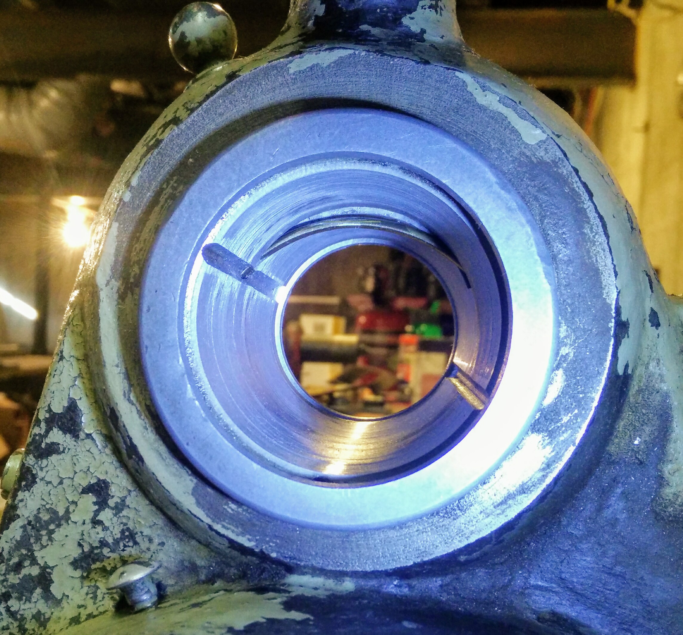
Here you can see the front outer race. Notice the oiling ring arched across the top and the two oil grooves running down the sides. At the bottom is an oil return channel that allows excess oil to run back into the reservoir. Two collars, one at each end, thread onto the bearing to catch the oil and direct it to the return channel.
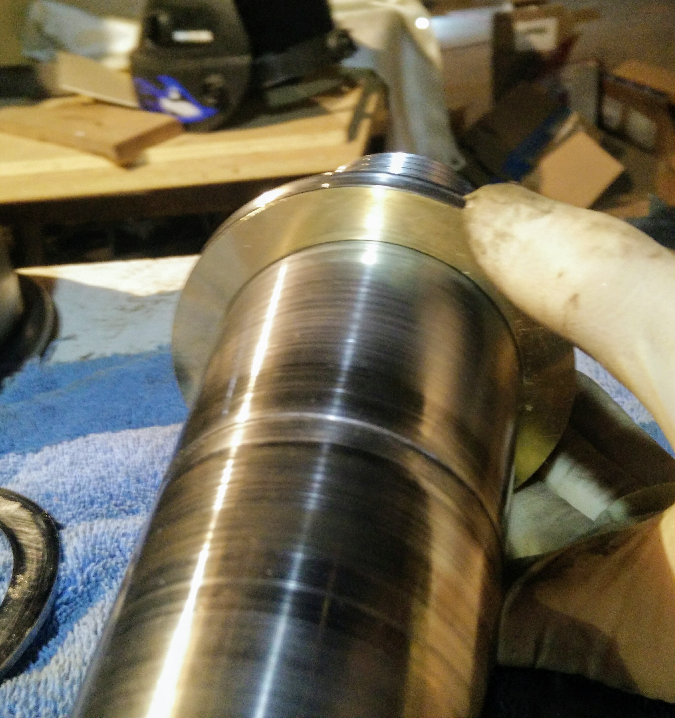
This photo shows both the radial and axial thrust surfaces of the bearing. The inner, tapered surface of the bearing takes the radial load on the spindle; the face of the bearing takes the axial thrust. Both are in pretty decent shape, considering their age — a few grooves but no severe pitting or wear.
The rear outer race is in similar condition. This race has integral oil catches instead of using collars like the front bearing; this is because this bearing takes hardly any axial load. The rear face of it does take axial load for cuts traveling away from the spindle towards the tailstock; however, those are not often done because the force also pulls the tapers in the spindle bearings apart, increasing the play in them.
Since these are both in nice shape, all I did was stone them lightly to remove any burrs. This must be done carefully — the stone must be kept flat against the bearing surface so it has many points of contact with the bearing and does not deform the bearing surface. The oil grooves are also stoned to remove any sharp edges.
Adjusting the rear bearing
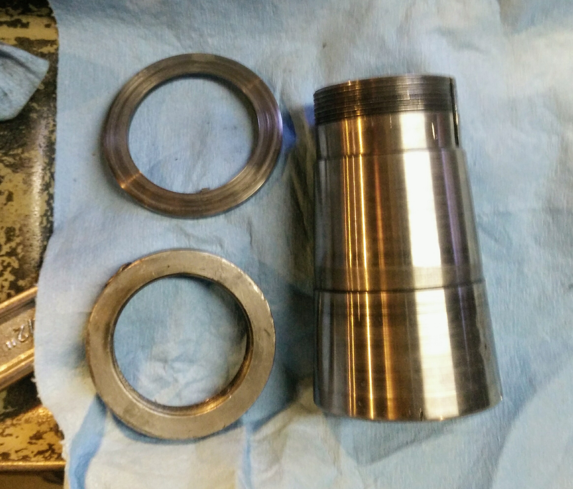
The rear inner race is held in the rear bearing with a thrust washer (top) and locking threaded collar (bottom):
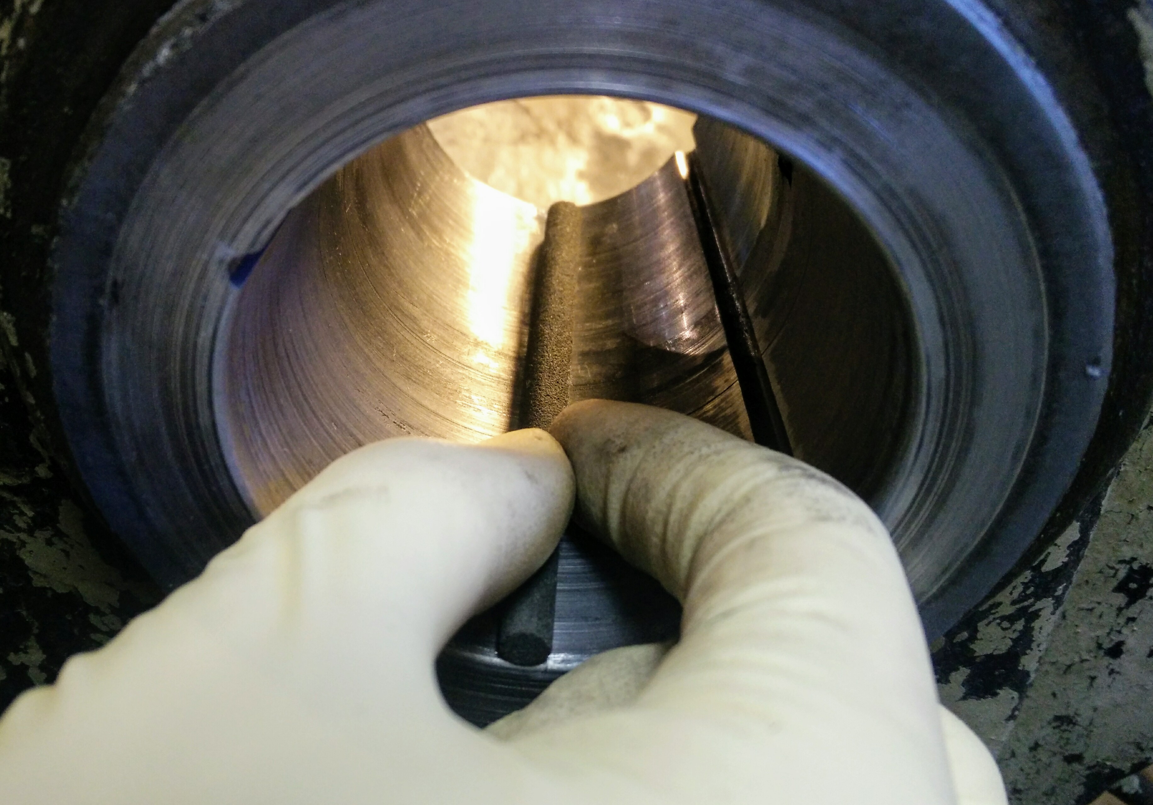
While it is separate from the spindle, inside the bore of the rear inner race is a key that fits into the spindle so that the two rotate together:
Both bearings have a 4° taper to them. Equipped with this knowledge and basic trigonometry, we can convert the axial play in the bearing into radial clearance: multiply the axial play by the tangent of 4° and you get the radial clearance. To spare you the horror of remembering high school math, I'll get right to the point: 5 thousandths (0.005 inch) of axial play gives about 3.5 tenths (0.00035 inch) of clearance per side. (For scale, a piece of paper is 3-4 thousandths.)
This clearance gives space for the spindle oil to form a hydraulic cushion that will keep the bearing races separate even under heavy loads. The exact clearance you need depends on the viscosity of the spindle oil and the speed at which you intend to run the spindle, but this about what the old farts on practical machinist are telling folks is a good clearance, so I'm going to go with it.
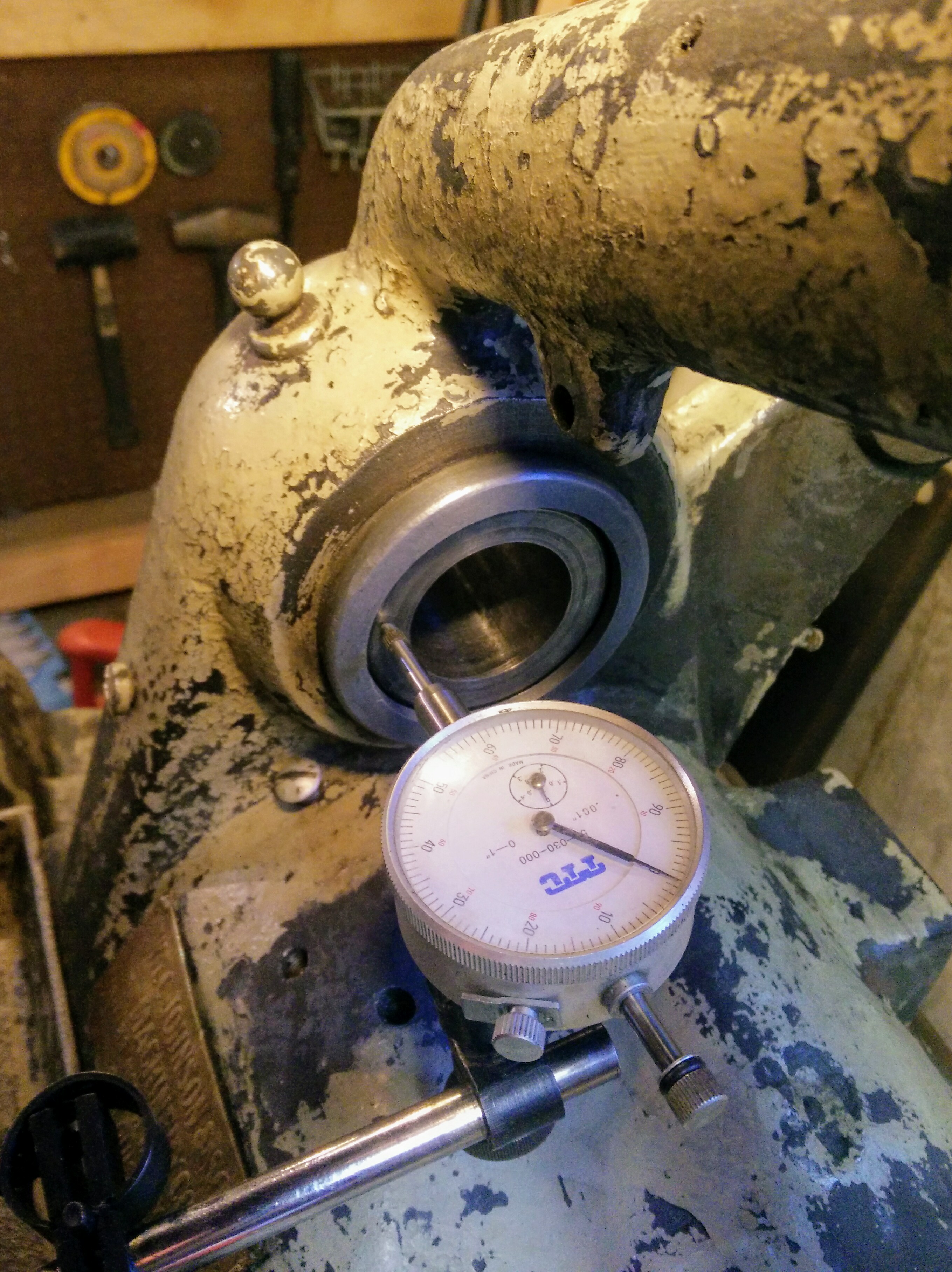
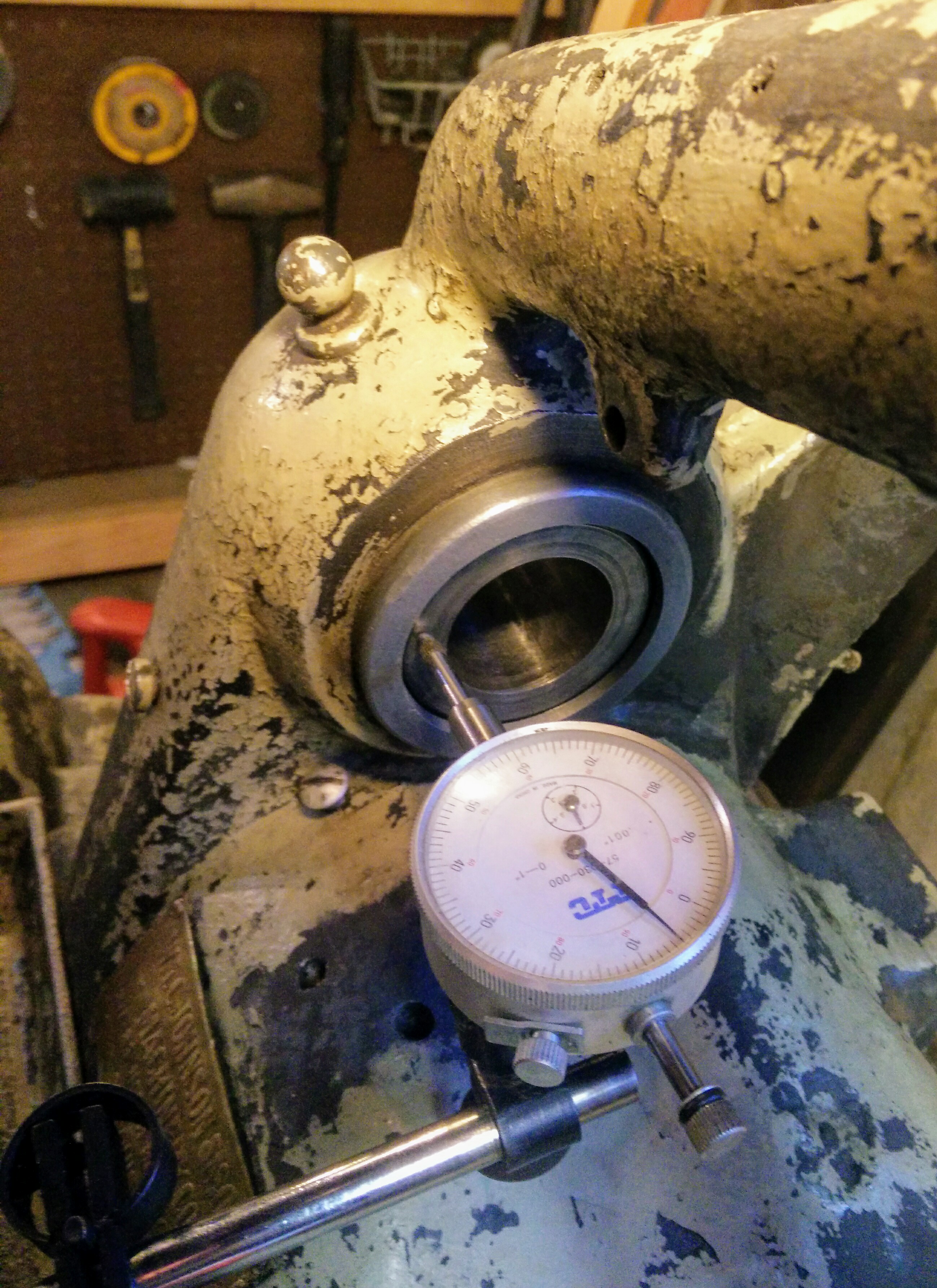
Measuring axial play is done with the inner race fitted dry into the outer race. Fit the inner race all the way into the outer race so you cannot turn it, put on the thrust washer, and tighten the collar onto the end. Using a dial indicator, you can see how much the inner race moves when the collar end is pushed on. Adjust the collar until you get the clearance you want!
Locked into the outer taper:
Five thou on the dot:
(Anyone who has tried to take photos of dial faces in a shop should appreciate how difficult it was to get those photos to come out. There's an invisible hand hovering to keep the overhead lights from blowing out the indicator faces.)
Once the collar is set right, tighten its setscrew so it cannot turn.
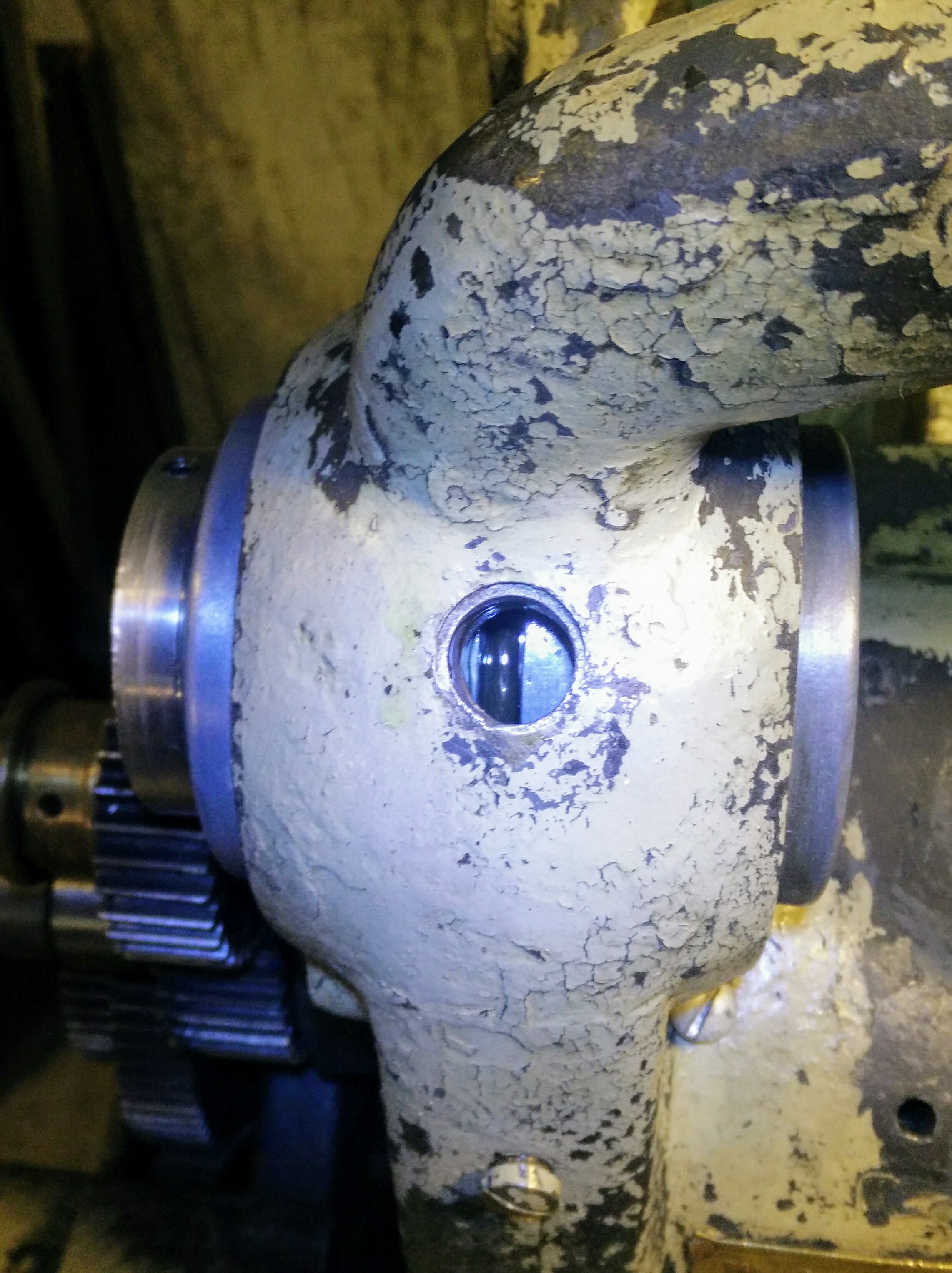
Remove the inspection cover and squirt a healthy amount of spindle oil over the oiling ring to prevent a dry start to the bearing:
To allay any of your concerns, a separate collar on the spindle tightens against the collar on the rear inner race, ensuring it cannot slide back and lock into the outer race's taper.
Tada! One bearing done, one to go. How hard can it be?
Measuring the clearance on the front bearing
Since the subheading isn't "Adjusting the front bearing", you may have correctly guessed that this bearing is slightly more complicated to adjust. The front inner race is part of the spindle itself and is designed to take a significant amount of axial thrust, hence the complexity.
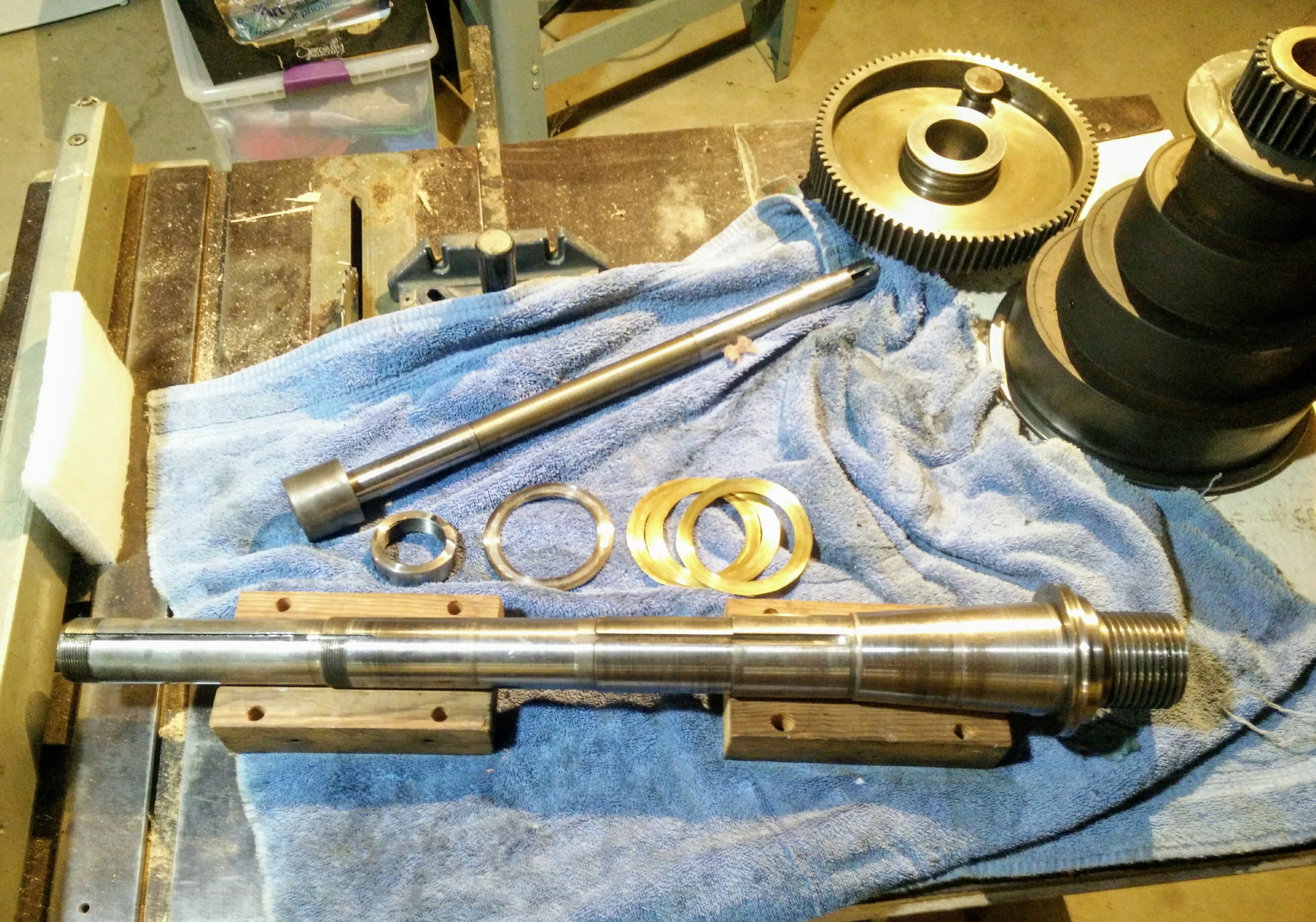
To get our bearings, here is a picture of the spindle itself:
Top to bottom, left to right: the big spindle drive gear, the back gear shaft (to be explained later), the cone pulley where the motor belt attaches, a collar for the spindle, the hardened spindle thrust washer (silver) and thrust shims (brass), and at last, the spindle. To the right is the front inner bearing race; the key slot to the left of it is for the drive gear and the key slot all the way at the left end is for the key in the rear bearing inner race.
None of the two threaded collars on the spindle adjust the front bearing clearance; instead, it is 'adjusted' by shims between the thrust washer and the thrust face on the spindle. We need to measure the gap so we know how much shim to put in. To do so, we install the spindle and thrust washer.
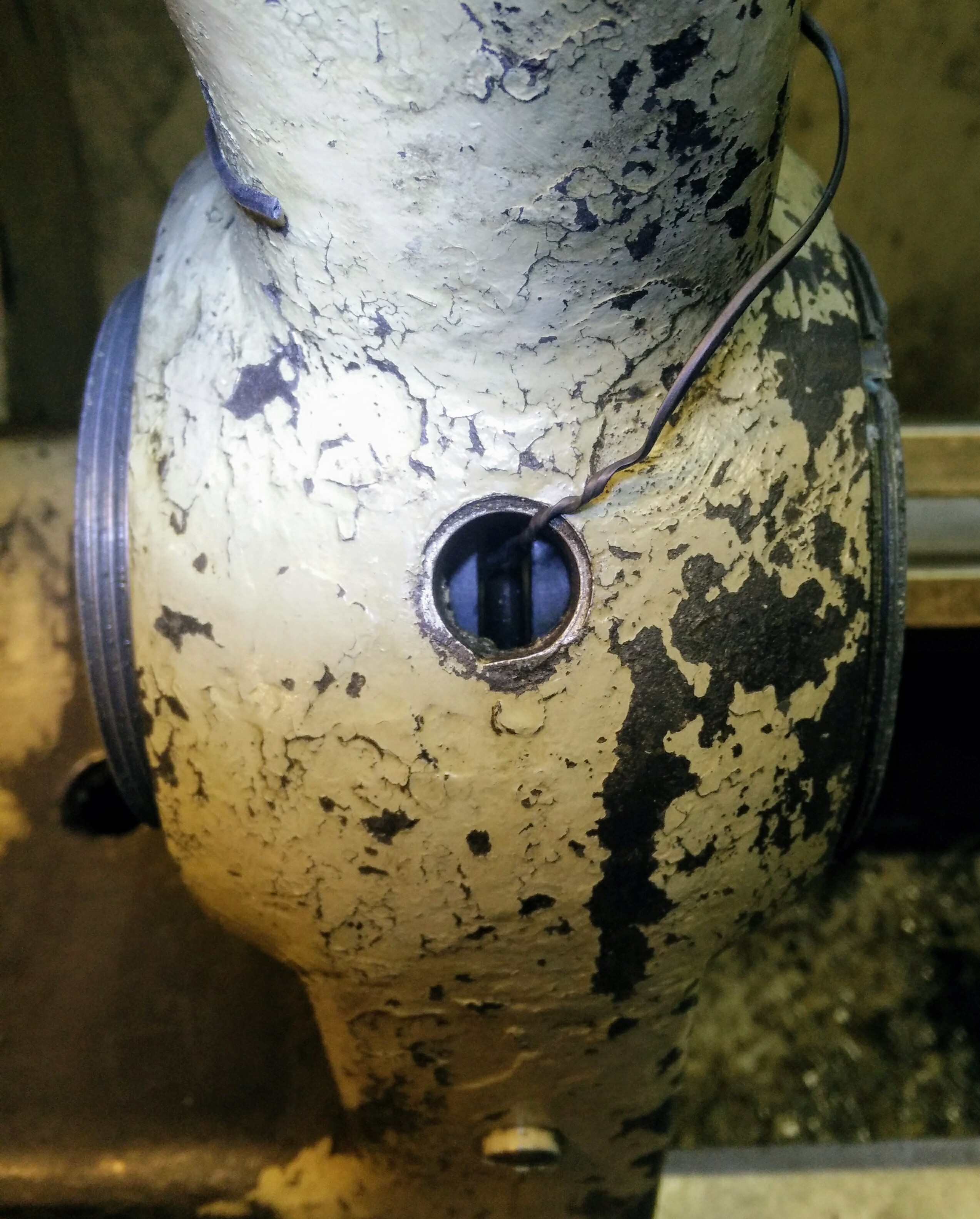
When installing the rear bearing, you can use a finger to push the oiling ring out of the way. For the spindle itself, there's too much going on, so I hooked it with a bit of wire:
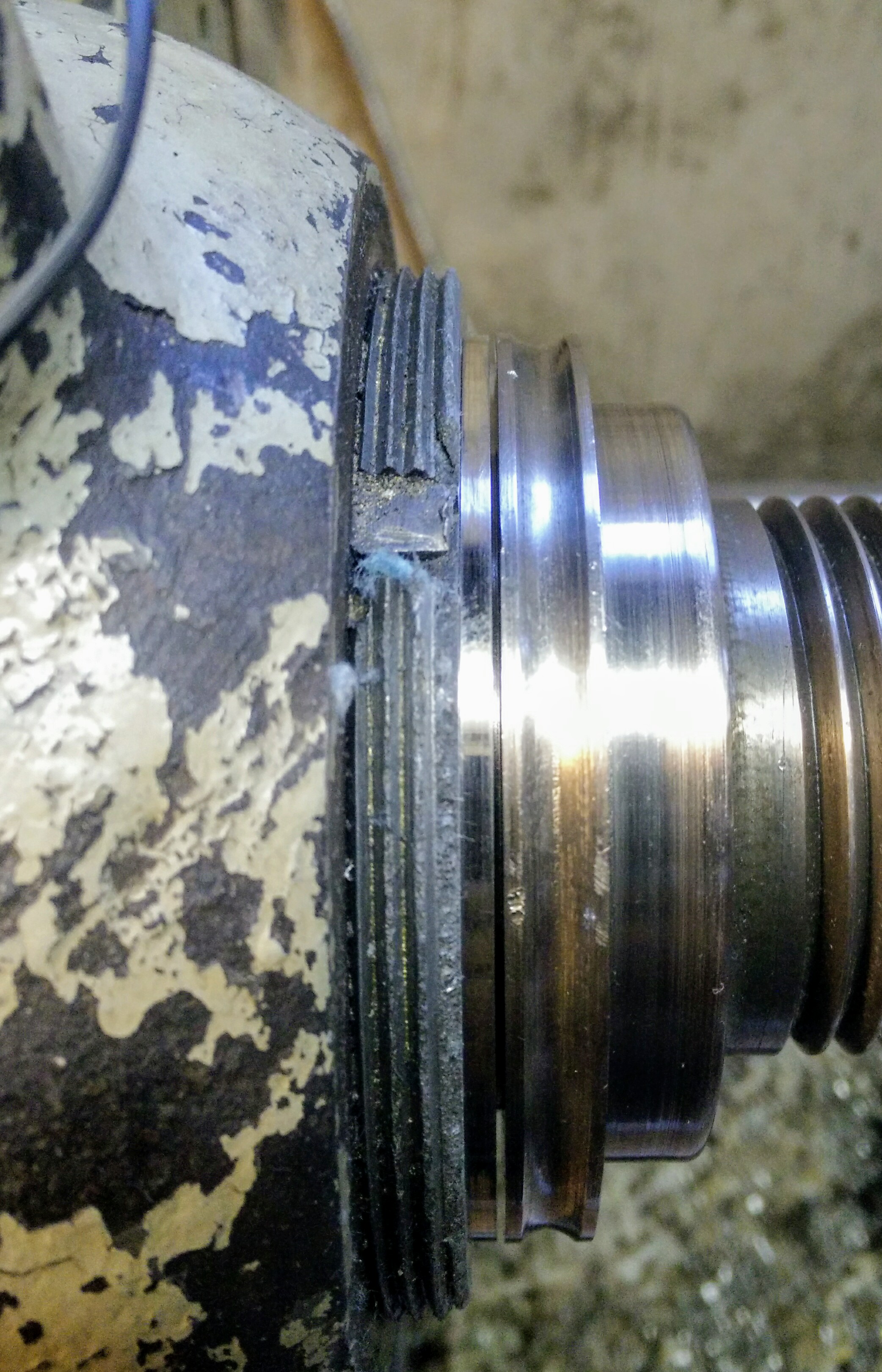
Once the spindle is slid in to the rear bearing, we measure the gap between the thrust face and the thrust washer:
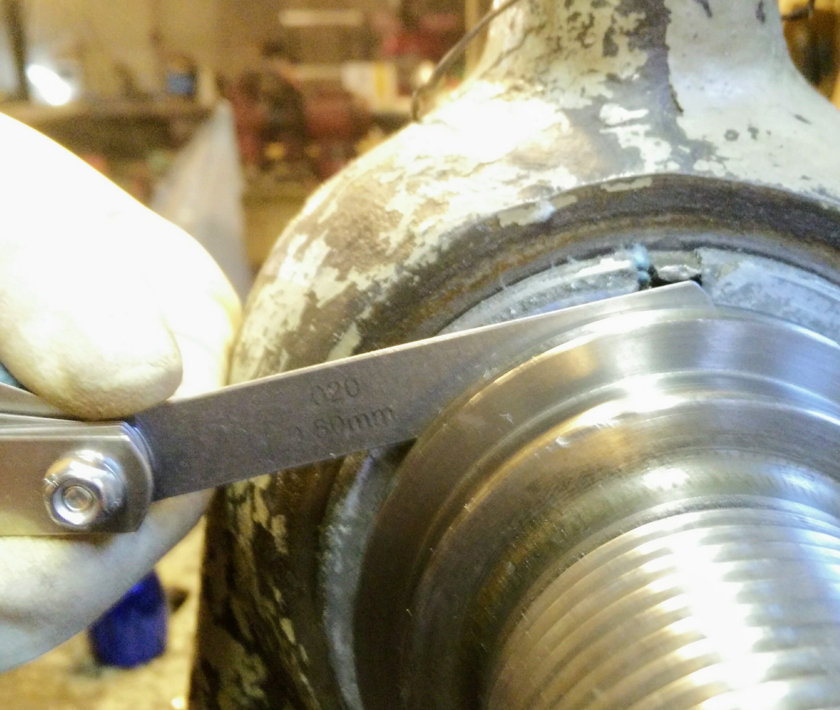
Some people recommend leaving the washer out when measuring and computing the shim thickness later, but I don't like that for two reasons. One, the face of the outer bearing race wears only where the thrust washer turns against it, so it eventually develops a hollow that is hard for feeler gauges to measure. Two, feeler gauges only come up to about 35 thou, so you have to stack up a bunch since the thrust washer is about an eighth of an inch (125 thou) thick. This introduces room for error both in getting grit or oil between the gauges and in adding up the values afterwards. Measuring between the thrust washer and face avoids both these issues as it wears evenly and the gap is much smaller. Be careful to not push the spindle back out as you're measuring.
A 20 thou gauge fits in several spots around the spindle:
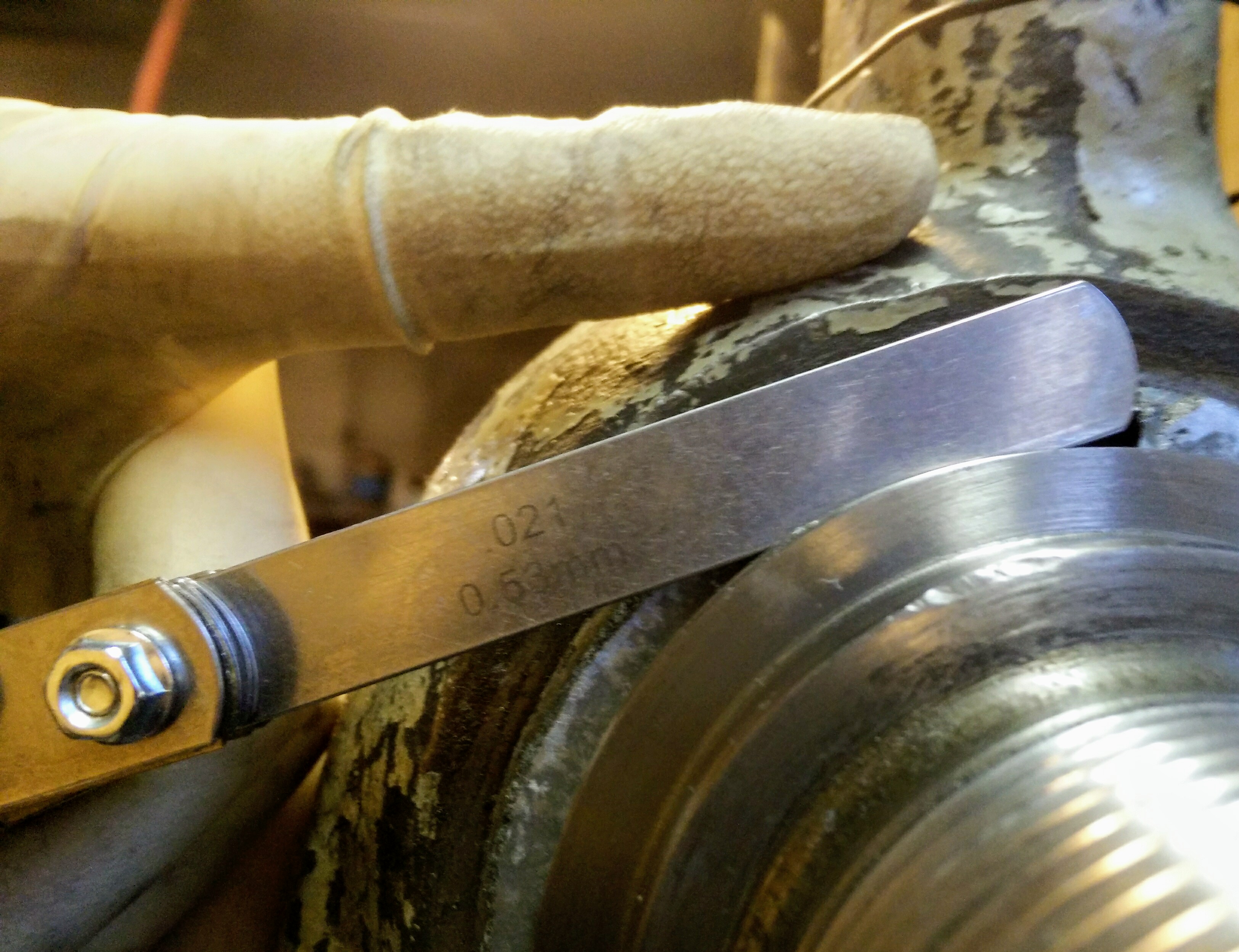
I can kind of get a 21 thou gauge to start in a spot or two, but not everywhere:
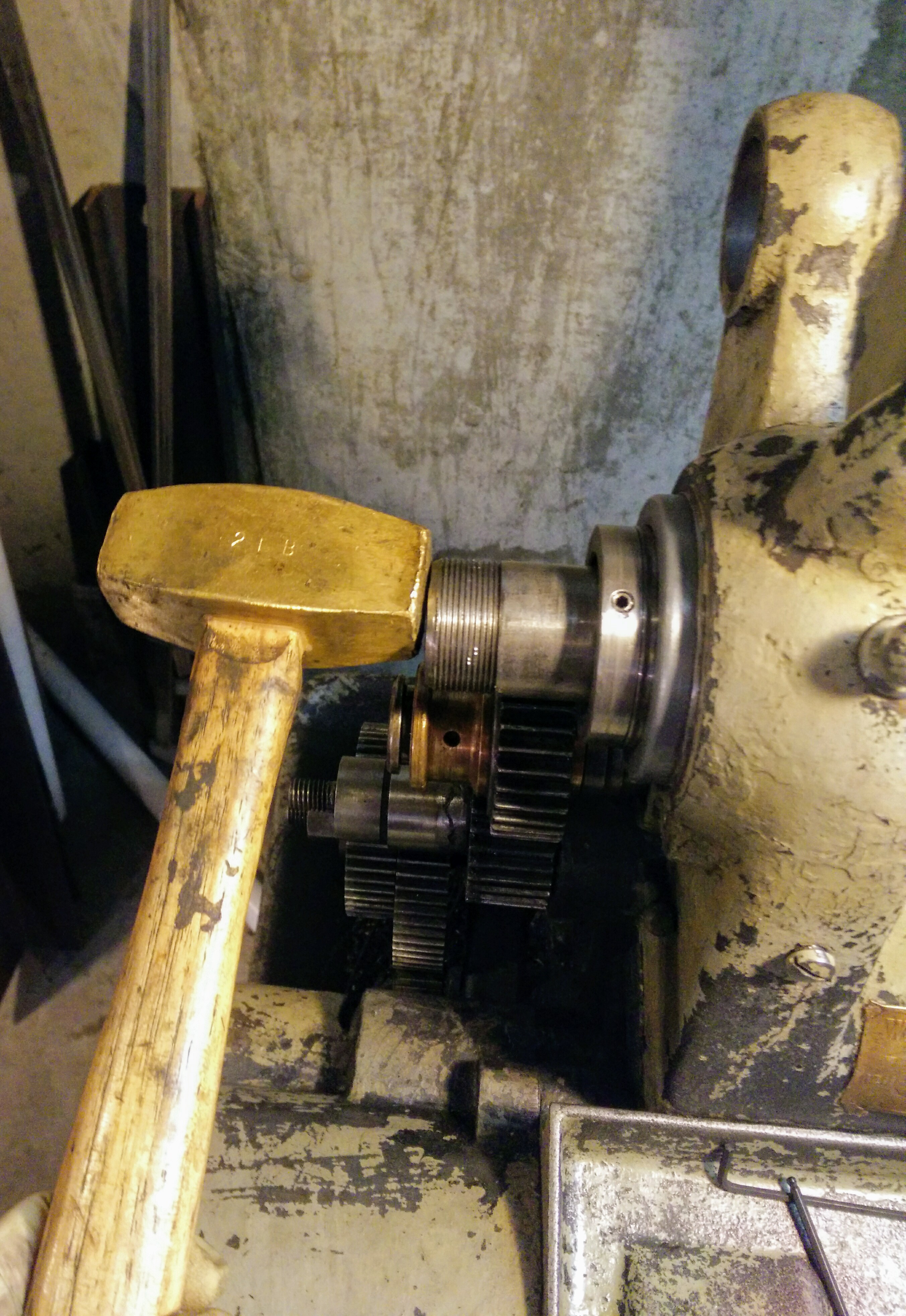
Measurement taken, we can now remove the spindle with a gentle tap:
In addition to the 20 thousandths gap here, we need to add an extra five thou for running clearance, same as the rear bearing. So we'll want a total shim thickness right around 25 thou.
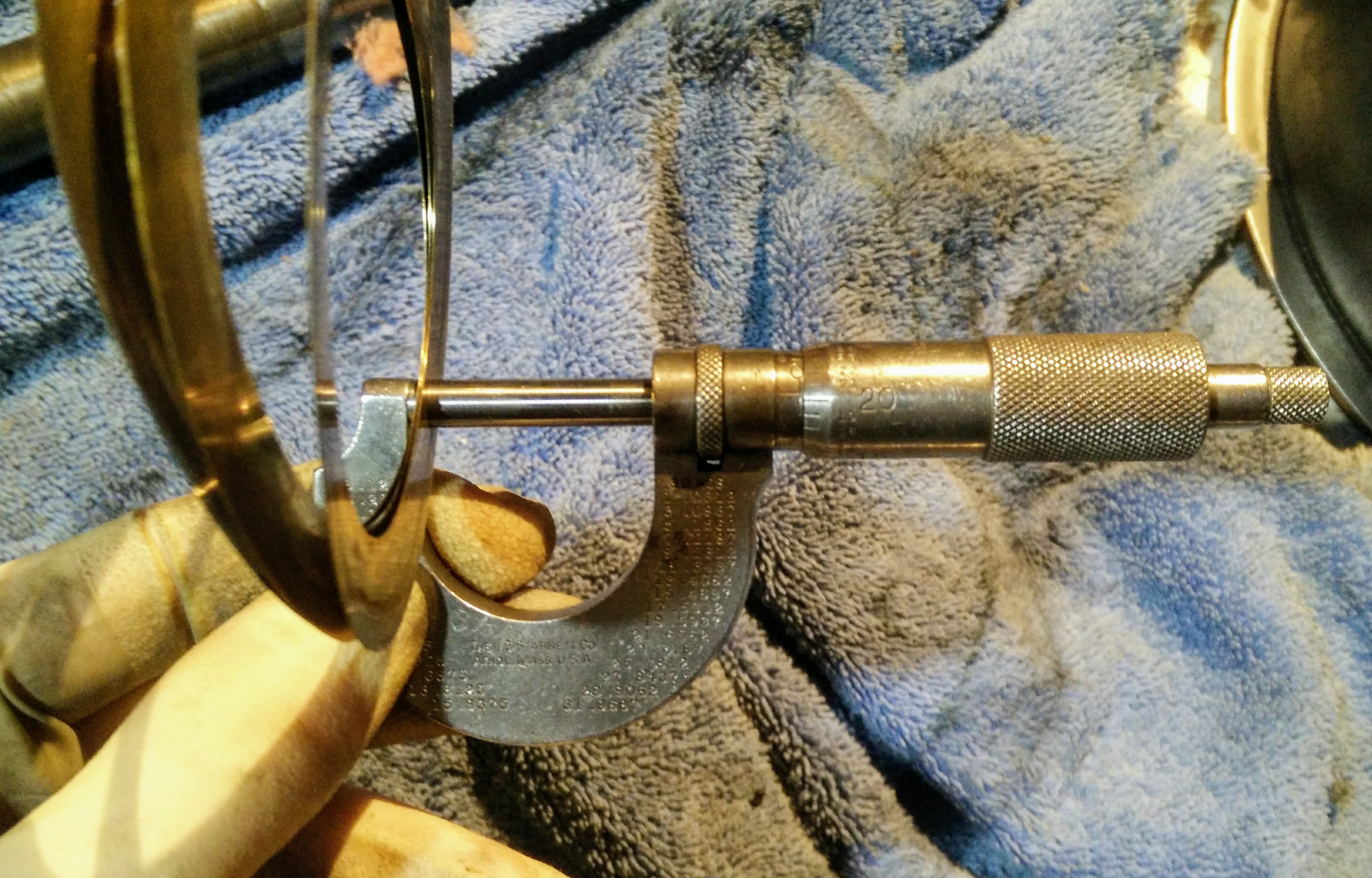
The existing shims measure a hair over 20 thou, hardly any clearance at all!
The shim stock I have only goes up to 15 thou, but fortunately one of the shims in the stack is 10 thou, so that plus a new 15 thou shim gets us exactly what we need.
Making a shim
Trace the thrust washer onto the shim stock with a scribe and rough cut with tin snips:
The proper way to finish this is to use punch dies to cut two beautiful, perfectly concentric holes to produce the washer. But I don't have any and they aren't cheap, so I found a more complicated way to do it instead.
Use a scroll saw to cut pretty close to the scribe lines:
I didn't have any brass-cutting blades, and the fine woodcutting ones work alright but start to grab the material as they dull. For the inside of the circle, I used a small drill and poked holes all the way around the perimeter, then used the saw to cut the lands in between the holes.
Since the thrust washer is file hard — files skate across the surface rather than cutting into the material — it can be used as a file guide. As the file cuts, it also forms the brass over the edge of the washer, eventually shearing the brass and leaving an edge that perfectly follows the washer itself.
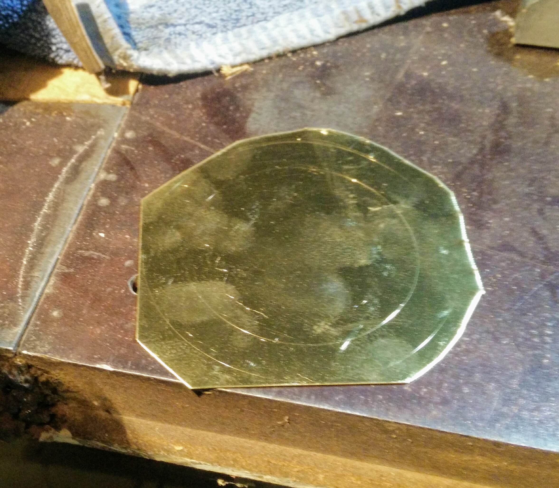
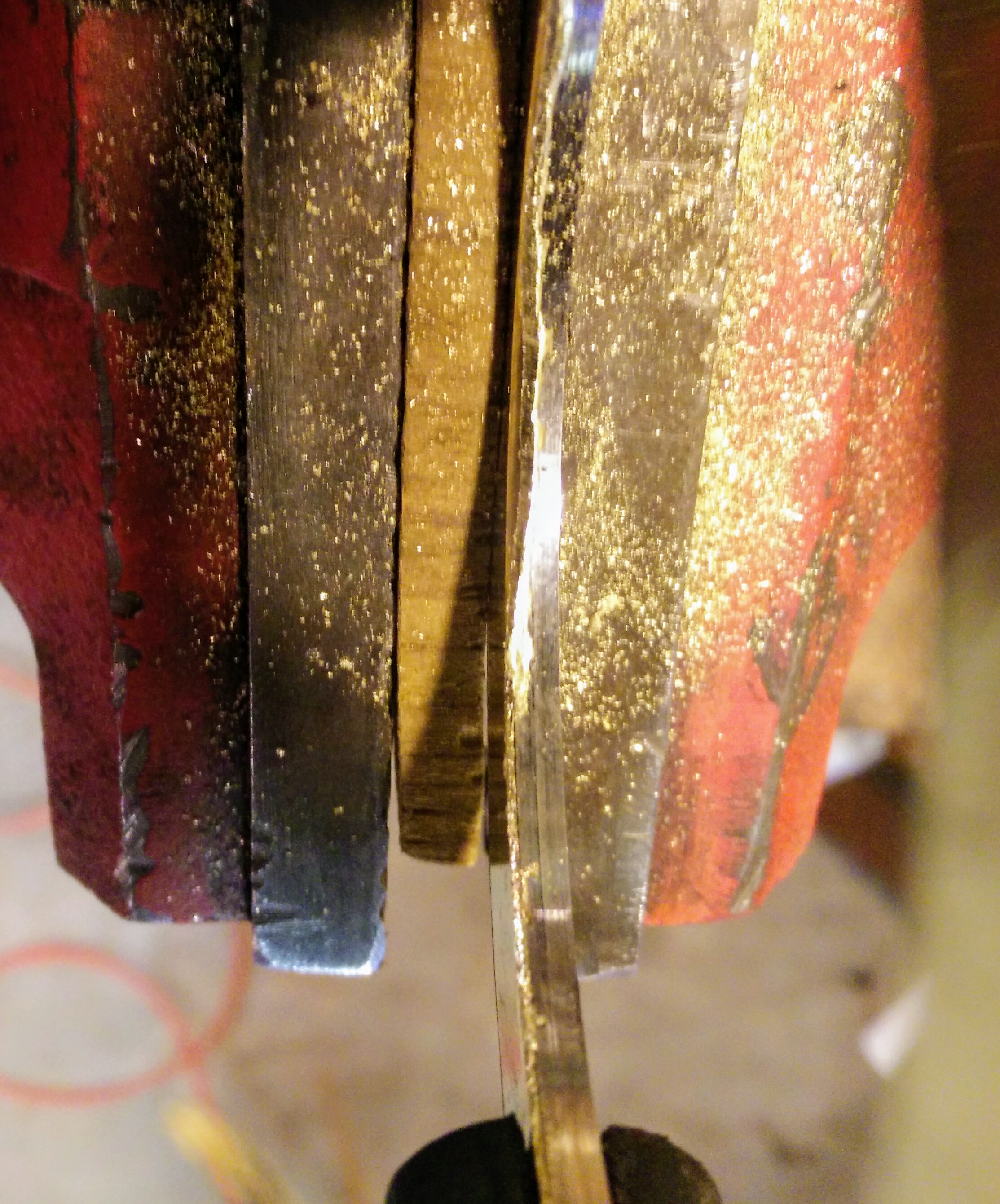
Then file a bit more to remove any burrs and smooth the cut edges and you end up with:
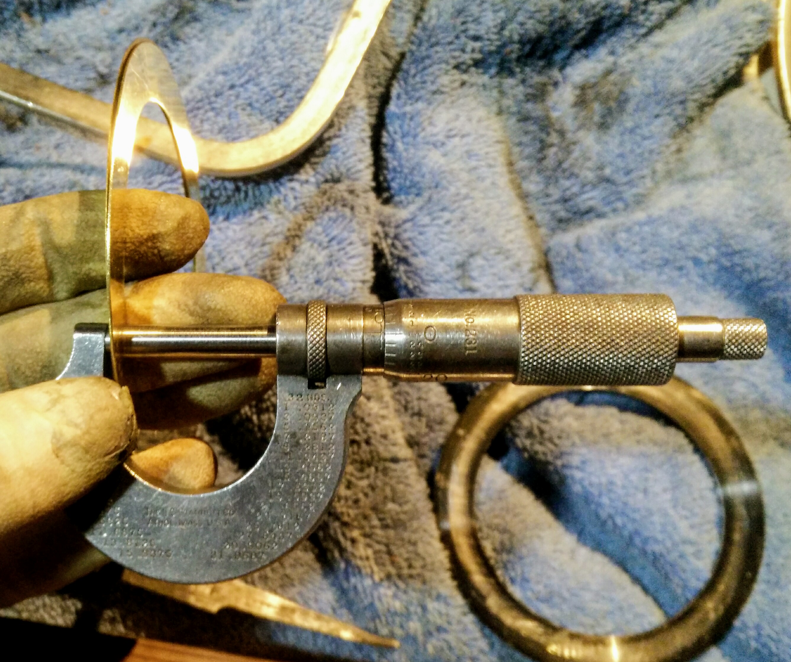
The new shim stack is right on 25 thou:
Installing the spindle
This is tricky because of all the things to line up in precious little space.
First, install the inner front oil catch ring.
Fit the drive gear and cone pulley roughly where they're meant to go and prop them up on wedges. Do not be deceived: that cone pulley is about 35 pounds. Also, make sure the drive belt is in the right place!
Guide the spindle through the front bearing, the drive gear bore, and the pulley bore. Before sliding it through the rear bearing, slip the collar that tightens the gear and pulley against the spindle in:
Installation is the reverse of removal: once the collar reaches its mating threads on the spindle, slowly turn it while tapping the nose of the spindle with a hammer until it is fully engaged:
Alternatively, use the tailstock to push the spindle in gently:
Next, install the rear collar that keeps the rear bearing from locking up and sets the total end play of the spindle:
Someone with a punch and a hammer deformed this collar enough that it does not thread on easily, so I may re-make it in the future when I have the thread cutting gears all ready to go. It's also heat-blued, which certainly raises some interesting questions about previous owners' approaches to maintenance.
At this point, we are finally ready for a test run! It ran quite happily in top gear for 20 minutes or so.
Installing the back gear
On my lathe, there are three points in the drivetrain where the angular velocity changes: a pulley reduction from the motor to the gearbox input shaft, a gear reduction or multiplication inside the gearbox, and another pulley reduction from the output of the gearbox to the cone pulley on the lathe. The back gear offers another two gear reductions, one from the small gear at the end of the cone pulley to the big gear on the back gear shaft and another from the small gear on the back gear shaft to the big drive gear on the spindle. While the direct-drive spindle speeds are in the 100-400 RPM range, the back gear speeds are in the 25-100 RPM range. They're mostly useful when cutting really coarse threads (but they also come in handy as there is a way to misuse them to lock the spindle rotation).
To allow the back gear to be engaged or disengaged, the shaft rotates on a pair of eccentric bushings. Turn the handle all the way left and the teeth don't mesh with the spindle gears; turn the handle all the way right and they do.
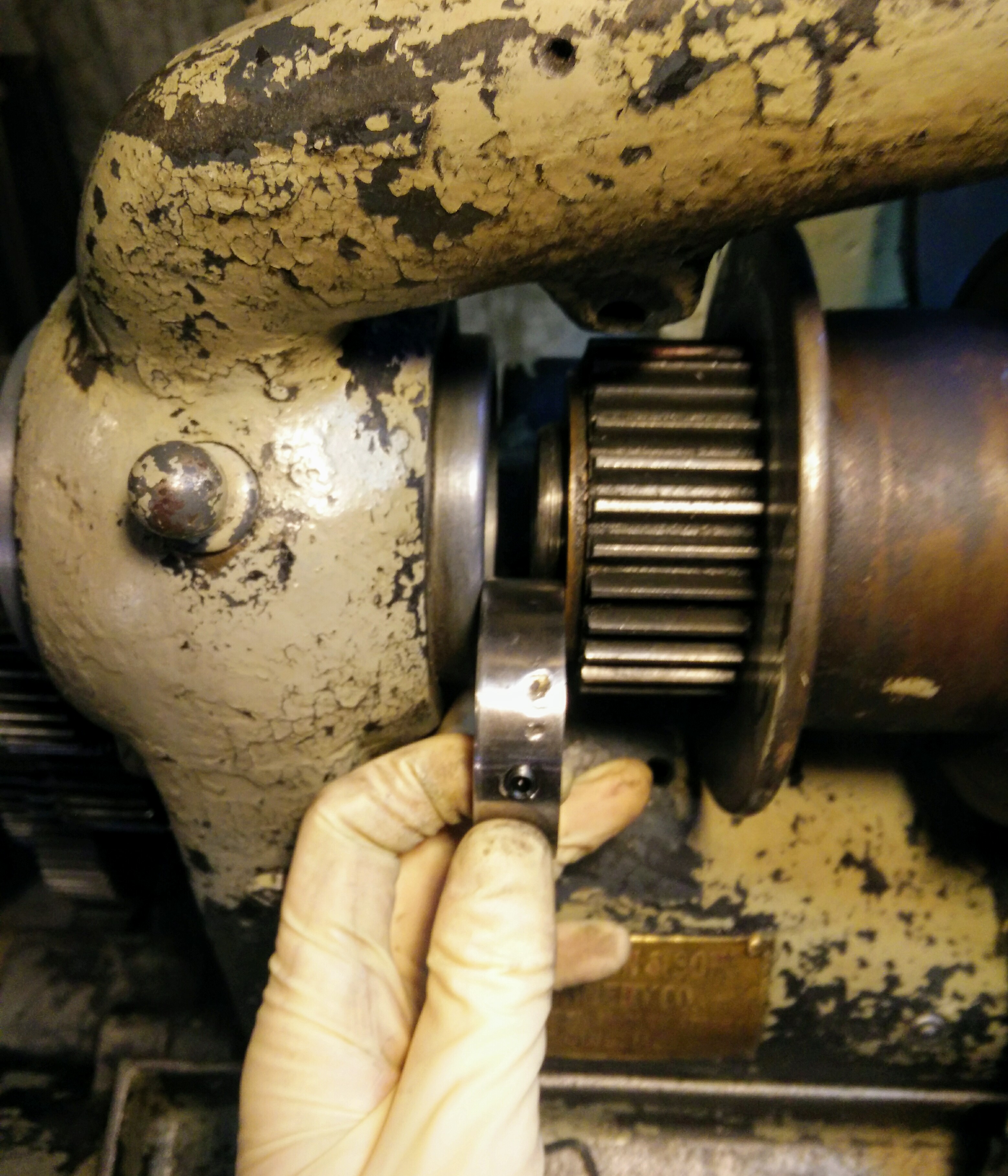
Fitting the back gear turned out to be complicated as it is a very tight fit against the spindle pulley:
I actually had to re-do the spindle collar adjustments in order to get it to fit. The back gear is at this point a sliding fit that will self-clearance in time.
Fitting covers and whatnot
The outer front oil catch ring goes on next. Whoever was in here with a punch before ruined three of the holes by punching through the ring, so this is also a candidate for re-making in the future.
In the meantime, rather than using masking tape as was done in the past, I used a few wraps of electrical tape to keep the oil in and the chips out:
A few gear train covers and gears go on in a very specific order:
The gear that transmits power from the feed forward/off/reverse mechanism to the leadscrew gearboxes:
And its cover. Note the holes above the two nuts: both of these align with matching holes in thrust washers inside the cover that oil their corresponding shafts.
Fit the spindle/back gear covers:
These come in four pieces and are definitely hand-fit to the lathe. Here you can see the feet on one of them and just barely make out century-old grinder marks:
The old trick of getting all the screws started before tightening any of them really comes in handy here. A couple have to be tightened in a specific order as the clearances are pretty tight in places.
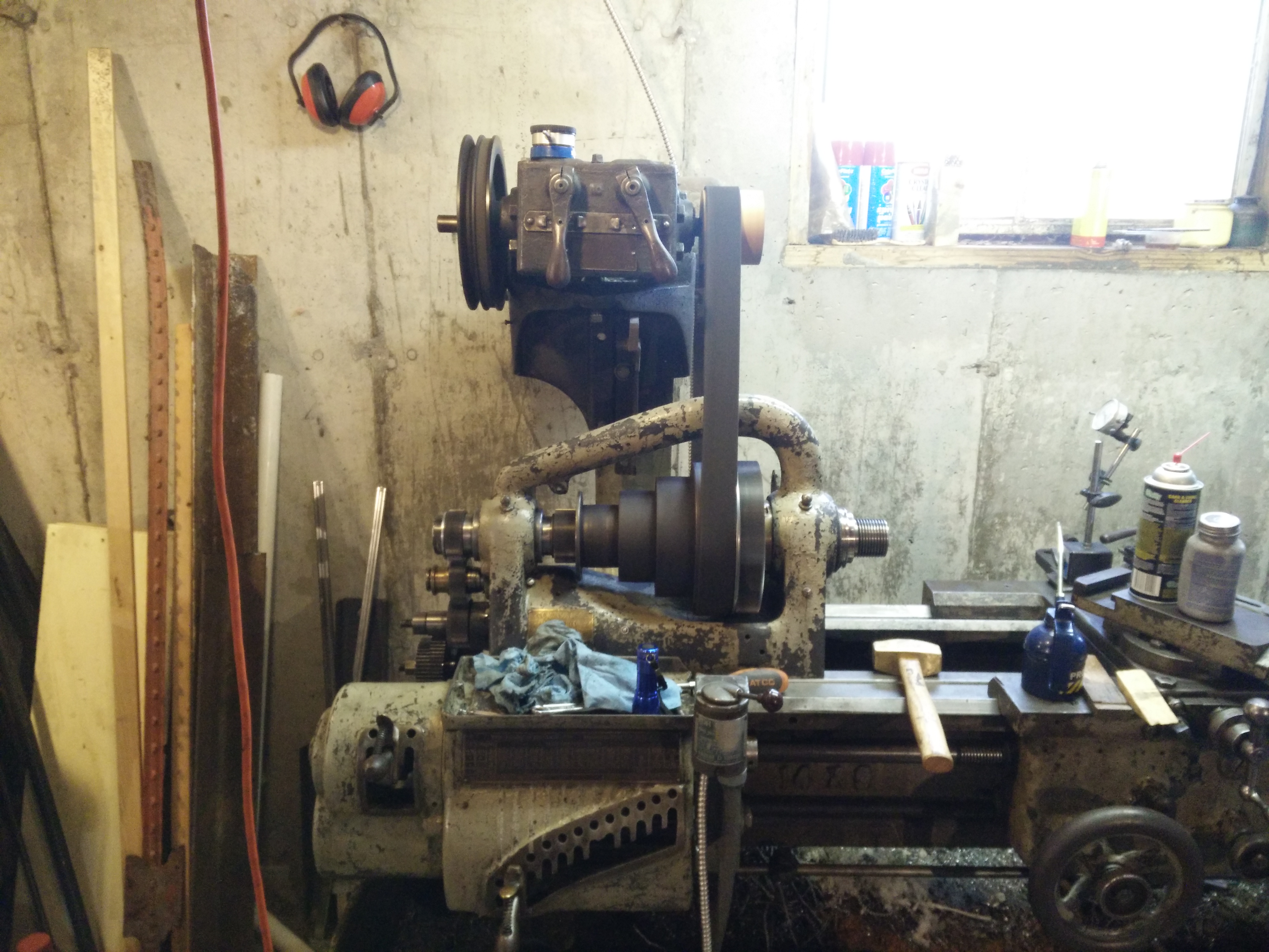
Done!
Finally, time to make some chips!
The lathe handled this quite well and even parting off went smoothly — that operation involves a fair bit of tool pressure to get a nice finish.
Unfortunately, the leadscrew gearboxes need work: one has a gear with a couple missing teeth (probably from someone crashing the tool into something) which I have a plan to repair and the other has trouble with the gears meshing, which likely means some bushings or shafts are worn out.
But, for the meantime, I intend to get some use from this tool and finish a couple other projects first!
Thank you! It was quite a nice machine in its day and has worked hard for a long time — someone paid a pretty penny to retrofit a gearbox onto it in the 50s, so I assume it spent at least 50 years on a shop floor making parts before getting sold off to a hobbyist for its 'retirement'.
Runout shouldn't have changed much, if at all, but now the bearings can take a load while still maintaining low runout! I spent a couple hours on it yesterday running in 4th gear which would have been outright impossible before — I'd have been lucky then to get 10 minutes on it before the spindle would freeze.
"spindle" and "freeze" are two words I really don't like seeing in proximity. I learned to cut on a similar, albeit burlier machine. American LaBlonde, rebuilt by the Army Corps of Engineers in 1919. My dad referred to it as a "total loss oiler." Thing was a hundred years old and would hold half a thou. Went to UW and they had similar machines for the undergrads to work on; they'd hold about fifteen thou. Turn 'em on and they made a sound kinda like a burr grinder.
This is how the feed gearbox sounds on mine now, but the spindle is very quiet. At this point, the lathe is not the source of most of my machining error. Hopefully that will change with some seat time! I think the wear in the ways and leadscrews is probably going to be what limits the precision of this machine. I could re-scrape the ways, have someone make a new leadscrew, and make myself a new cross-slide leadscrew and nut, but I'd probably be better off saving that money and buying a nicer machine instead. 15 thou tolerance is I think worse than a harbor freight drill press!a sound kinda like a burr grinder.
